Wright Bros' Flyer: Super detailing a Guillow's kit.

Ad: This forum contains affiliate links to products on Amazon and eBay. More information in Terms and rules

Skyediamonds

Staff Sergeant
1,080
441
May 26, 2018
Fellow members and guess: At the suggestion of Wurger, I'll be posting a series of builds of my Guillow's kit of the Wright Bros' Flyer from the initial frame up to the finishing touches. For those not familiar, Guillow's kits are wooden kits designed expressly for rubber powered flight or small electric motor conversions. The method of construction basically follows a well-known "stick-n-tissue route in which the skeletal frames are covered with tissue and painted in the colors of choice along with the appropriate decals. In this case, the Wright Bros' model will be taken to another level of construction of super detailing such that it will be easily seen that this can be applied to almost all kits of this genre.

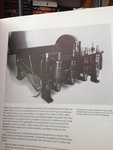
I thought it best to start off this build thread by showing the completed model and then we'll start at the very beginning of the initial frame up and go from there. All things were made from scratch, including the engine, the chain drive system and all of the special linkages.

I hope everyone will sit back and enjoy the "show" and all comments are welcome. Although this is a WWI airplane, Wurger suggested that it would be of value for all of us at this WW2aircraft site.

IMG_2447.JPG


IMG_2706.JPG


Thank you,
Skye
 
Last edited by a moderator:
Gary... your pics haven't been uploaded properly. I can't see them neither here nor with the picture browser of the Admin panel. Please edit your post and re-upload these images.
 
Interesting project, Skye (Gary⁉️).
What scale is ... 1/48 ?. It will be enriching to see the step by step of how you came to that good end.

Saludos :thumbup:
Luis Carlos
 
Last edited:
Gentlemen, Good afternoon. It seems I've got a lot of people's attention with this one. I'll try to address issues as they crop up from time to time. Please, all comments are welcome and for all to enjoy. Wurger, I don't know what else I need to do to upload the pictures. Judging from the reaction of you and others, it seems as though the pictures are showing up just fine. I do need to know however, if I should post them full size or thumbnail. Please let me know and I'll follow your lead. I would also like to know if there is an editing feature for me to correct any mistakes or to rephrase my commentary for clarity.

The model is a Guillow's kit that is supposed to be 1 1/2th scale. There are plastic kits out there and they've been around for decades. I know, because I built one of those plastic kits when I was a kid (I'm 69 now). For those who are not familiar with all of the detail surrounding both the Flyer and the kit itself: The Flyer is approximately 27" in wingspan and made out of all wood (mostly balsa) with td kits since the early 1930's or even before.

As with most models, plastics included, it all starts with research. I wasn't too surprised to find out that there was a lot of misinformation and lack of information on the Wright Bros' Flyer. This has long been acknowledged by anyone who is an aviation enthusiast. What surprised me was the vast amount of misinformation from supposedly knowledgeable sources. I will share with you most of what I have discovered about what is accurate and what is not. I'm hoping we can have a dialogue on this portion as well.

***Finally, most importantly for all concern: I live in a small apartment and I only have common household tools such as scissors, tweezers, pliers (needle nose), a small hammer, and that all ubiquitous #11 X-Acto blade, and other assorted common items found laying around the home. No exotic tools, no complicated assemblies, and no 3-D printing whatsoever. So, all of the accessories such as that engine you saw, was created by simple tools, balsa wood, and some plastic, and lots of imagination.

I'll start the build by revealing some of my research and which is valid and which I found sorely lacking in accuracy. One thing's for sure, lots of pictures of the Flyer on display at the Smithsonian was used. They were obtained from books, publications and other assorted sources.

So, let's get started with the research...... Can anyone spot some of the discrepancies?

698.JPG 760.JPG 755.JPG708.JPG 694.JPG 709.JPG IMG_2120.JPG 013.JPG 754.JPG
 
Wurger, I don't know what else I need to do to upload the pictures. Judging from the reaction of you and others, it seems as though the pictures are showing up just fine. I do need to know however, if I should post them full size or thumbnail. Please let me know and I'll follow your lead. I would also like to know if there is an editing feature for me to correct any mistakes or to rephrase my commentary for clarity.

Here is a screenshot of your post #5 and what I can see on my screen. No pics displayed but only the blue links. When clicking them I get an error message. Other images posted here are displayed fine. I have checked on the lost images in the Admin panel and can't see them there too. The list of posted shots by you doesn't contain them. It means these aren't attached properly. Additionally I checked on them using my smartphone. There is the same.Therefore I asked for re-attaching of them . There is the option at the bottom of your each post. I marked it red in the screenshot. Click that and you get the edit window. However it is for a quick edition of post actually. For full editing click the More Options button at the bottom of the Quick Editing window. There you may edit, not only of your text but also attached pics. The full list of attached images with buttons for deleting /attaching/displaying is down so you have to scroll the screen down to see that. Regarding the full size or thumbnails... if your pictures are large I would suggest the thumbnali option for displaying. If these aren't too large ( up to 1600 pixels in the width ) you may use the Full Image button for displaying of them. I hope it can help.

invalid pics.jpg
 
Wurger,
I sincerely thank you for your reply and offering of help in my finding the editing button and the use of thumbnail sized pictures. If anyone else should have any troubles or would like to comment on this build itself, please feel free to express yourselves and let's have a great time and great exchange of ideas and building techniques.

As stated in my previous post, there are a lot of misinformation pertaining to the Wright Flyer. As everyone knows, the Wrights did not keep any blueprints or records of their aircraft or make drawings. Literally everything was "on the fly." One of the previous pictures shows a full sized replica with natural wood propellers. The Wrights had their propellers painted overall medium gray. What is also not widely known is the Brothers also had the propeller tips covered in fabric to help prevent splitting of the wood.

Finally, everyone is enthralled with all that rigging and who can blame 'em? What is often unknown and missing in 90% of all the models,of the rigging; also included longitudinal rigging. That is, rigging from the front struts crossed over to the rear struts and back again. This type of rigging is similar in what we all see on the cross rigging between the outer wing struts and the inner cabane struts. This type of rigging is used to help orient the wings in incidence. The wing warping will definitely be covered quite extensively and should help eliminate any questions on how it works. The last outer struts were not rigged longitudinally and this is due to help the wings "twist" for warping. Lastly. many modelers forget about the rigging of the rudder such that it is "automatically" functional and dependent upon, the pilot's sliding cradle and is connected via bellcranks.

Of course, we all know that the Wright's mechanic, James Taylor, made a carburetor out of a tomato soup can, that is is also replicated on the model. So, a bit of building here and there with some additional research and we've off.

Let's start right away with that "attention-getter," the engine. It's usually the first item people look for and if done right, comes out looking like a gem and really sets off the rest of the model.

My next post will start with the actual build with an occasional commentary and some references thrown in for good measure and "entertainment" value.
 
The Guillow's kit provided me with just the solid block of balsa for me to create an engine. For the engine alone, that's not much to go by, but we'll make the best out of what we're given. The next picture shows my using my ever-present # 11 X-Acto blade to cut the block into size more suitable for the engine scale in relation to the size of the model itself. This is purely an eyeball guess as to what size would look best. I laid down the block and conjured up an image in my mind of the engine with all of the accessories and determined that a "slight" trim was in order. I promise you, from this point on, I'll keep my narrative to a minimum and we'll proceed rapidly.
 

Attachments

  • IMG_1919.JPG
    IMG_1919.JPG
    784 KB · Views: 150
  • IMG_3504.JPG
    IMG_3504.JPG
    1.2 MB · Views: 141
  • IMG_2970.JPG
    IMG_2970.JPG
    906.8 KB · Views: 142
After the block was cut to size, the block was lightly sanded. I determined that the engine has a slight bulge towards one side for clearance of the rotating crankshaft. So, I'm going to add small bits of balsa to help lay out the foundation to build up this area and cover in with simple Spackling Compound usually found in most hardware stores. I also masked off one side of the balsa block to keep it clean from the Compound and that will be seen later. *Important note: Once the Spackling Compound was applied to the block and over the tape, I immediately pulled off the tape before the Compound started to dry to avoid dry chips later on. I wanted a nice, clean line between the Compounded side and the bare balsa.
 

Attachments

  • IMG_2972.JPG
    IMG_2972.JPG
    553.8 KB · Views: 136
  • IMG_3461.JPG
    IMG_3461.JPG
    530.4 KB · Views: 134
Last edited:
The masking tape was removed quickly (in this case, I used Scotch brand tape, but it really doesn't matter which tape is used at this point). Then the Spackling Compound dried turning color from pink to white. This usually takes about an hour. I waited a bit longer just to be safe. I then sanded the Spackling Compound to a rounded shape. Now we have the basic engine block that we desired. In the next picture, I'm already enjoying what I love best, cutting up credit cards; or at least the unsolicited ones, to size that I need for the block.
 

Attachments

  • IMG_2363.JPG
    IMG_2363.JPG
    915.6 KB · Views: 149
  • IMG_2364.JPG
    IMG_2364.JPG
    945.8 KB · Views: 135
  • IMG_2365.JPG
    IMG_2365.JPG
    900.8 KB · Views: 147
Here, you can see the finished engine block with its rounded side. Next, the plastic is used to form a "plate" if you will, to help support the cylinders. Note too, that I scored down the middle to help me bend this card to a nice, crisp fold. This piece is then folded down to help make both a smooth top portion of the engine and an equally smooth side. ** Note, that the fold has an edge. This edge is left there on purpose and will be used to very good effect later on in the build. As you can probably surmise, I did a lot of planning and thinking well ahead of time before and during the build.
 

Attachments

  • IMG_2368.JPG
    IMG_2368.JPG
    838.2 KB · Views: 135
  • IMG_2365.JPG
    IMG_2365.JPG
    900.8 KB · Views: 138
  • IMG_2367.JPG
    IMG_2367.JPG
    879.6 KB · Views: 125
  • IMG_2371.JPG
    IMG_2371.JPG
    890.6 KB · Views: 148
  • IMG_3475.JPG
    IMG_3475.JPG
    708.5 KB · Views: 137
  • IMG_2372.JPG
    IMG_2372.JPG
    765.7 KB · Views: 126
Now we can take the balsa block and turn it on its sides to make the two side of the engine. Again, I'm using plastic, By making extensive use of plastic, I'm avoiding all that sanding, then filling in the wood grains, and sanding some more, refilling wood grains left over or missed the first time, sanding, and then priming. Goodness, there must be a better, easier and faster way of achieving the same results without all the hassles. Thus, the use of plastics from old, or discarded credit cards that do not have those embossed letters and numbers. It's important that the plastic be very smooth. It really doesn't have to be credit cards. It can be almost any type of thick, but smooth, plastic sheets. You could even purchase some from Evergreen or at your local hobby store, or at your local arts and crafts store. Now I'm tracing the outlines of the sides to the plastic and then using a simple set of household scissors to cut the plastic. It's far easier to use scissors than with a razor. Note too, that I'm leaving extra plastic for the "legs."
 

Attachments

  • IMG_2380.JPG
    IMG_2380.JPG
    733.1 KB · Views: 133
  • IMG_2381.JPG
    IMG_2381.JPG
    825.9 KB · Views: 132
  • IMG_2384.JPG
    IMG_2384.JPG
    505.8 KB · Views: 123
Prior to finishing off the two sides, I'm now drilling out a small hole on one side of the "engine" to accept the gears and chain drives. To do this, I used a small Dremel tool with a router attached to the end. Then I used a black marking pen and filled in the cavity with black ink. Next, I taped off the end that was drilled out and filled with black ink. You'll see how all this comes together..... Trust me.
 

Attachments

  • IMG_3476.JPG
    IMG_3476.JPG
    1.1 MB · Views: 145
  • IMG_3479.JPG
    IMG_3479.JPG
    844.3 KB · Views: 125
  • IMG_3480.JPG
    IMG_3480.JPG
    1.2 MB · Views: 125
  • IMG_3484.JPG
    IMG_3484.JPG
    733.3 KB · Views: 121

Users who are viewing this thread

Back