Wright Bros' Flyer: Super detailing a Guillow's kit.

Ad: This forum contains affiliate links to products on Amazon and eBay. More information in Terms and rules

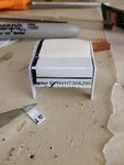
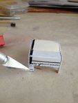
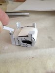
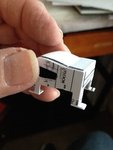
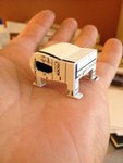
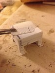
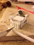
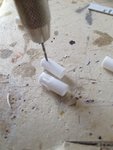
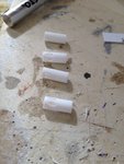
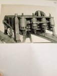
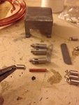
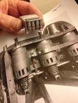
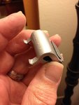
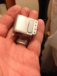
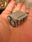
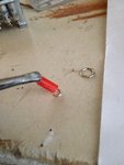
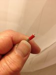
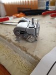
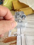
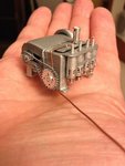
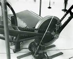
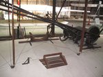
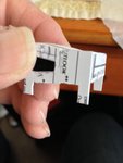
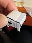
The two sides are now cut, complete with their respective support legs. One side has an additional hole cut out for the gearing mentioned previously. In this photo, I removed the tape to show the plastic side and how it meshes with the block. At this stage, it's really starting to look like a bona-fide engine. Whoa.
 

Attachments

  • IMG_2384.JPG
    IMG_2384.JPG
    505.8 KB · Views: 38
  • IMG_2390.JPG
    IMG_2390.JPG
    999.6 KB · Views: 40
  • IMG_2392.JPG
    IMG_2392.JPG
    591.7 KB · Views: 56
  • IMG_2394.JPG
    IMG_2394.JPG
    596.7 KB · Views: 40
Last edited:
Now it's time to give the support legs some dimension and "sturdiness." Small pieces of plastic were cut to both length and size to match the original legs and glued into place. Additional small squared pieces were cut and glued to the bottom of the legs to give it support brackets to which the engine will be bolted to the wing. Sort of looks like a pair of feet at this point.
 

Attachments

  • IMG_2395.JPG
    IMG_2395.JPG
    867.2 KB · Views: 36
  • IMG_2396.JPG
    IMG_2396.JPG
    829.9 KB · Views: 36
  • IMG_2397.JPG
    IMG_2397.JPG
    1,000.2 KB · Views: 37
  • IMG_2403.JPG
    IMG_2403.JPG
    1,017.3 KB · Views: 45
Starting to look like a Wright Bros' engine, eh? Best part? No sanding or filling or priming whatsoever. It's almost ready for painting as it is. We'l just add a few extra details to give it that "finesse."
 

Attachments

  • IMG_2404.JPG
    IMG_2404.JPG
    1.1 MB · Views: 38
In this case, I'll add a small amount of Spackling Compound to the base at the corners of the "feet" to help round out the sharp corners and give it the illusion of it being welded in place. Next, comes the plate that sits on top of the engine. Notice is also has rivets. To make the rivets, and due to the thick and hardness of the plastic, I use a very small hammer to gently "tap" a dull "T" in on the back to force out the rivets on the opposite side. You can easily see the results on the next photo. Not bad, eh? I took my time and carefully measured on the back the spacing of all of the "rivets" to ensure a nice finish. This plate will then be glued to the top.
 

Attachments

  • IMG_2405.JPG
    IMG_2405.JPG
    44.7 KB · Views: 44
  • IMG_2406.JPG
    IMG_2406.JPG
    1.5 MB · Views: 40
  • IMG_2410.JPG
    IMG_2410.JPG
    1.4 MB · Views: 44
I apologize in advance for not taking pictures of what happened in my last assembly of the plate the this next step of fabricating the cylinders. I just got carried away with the build. Suffice to say, that small "edge" on the fold from the previous posts was used to glue on another separate flat piece of plastic to be used as a support for the cylinders. The cylinders were from Evergreen's plastic tubing cut to length. The length of the cylinders were cut using the eyeball method of determining what looks to be right. It's from this point, that I decided to take this little engine one step higher than some of the wooden kits that are out there and, instead of using marking pens to draw simulated cooling holes to the cylinders, I decided to actually drill out the cooling holes. To accomplish this, it's really simple. Just use a pin vise, this is one of my rare specialty tools that serves as a small hand-drill with very small drill bits. Carefully drill out two holes. One on each end. Then use a fresh # 11 X-Acto blade, cut the length of cutout between the two holes to achieve a 'racetrack" pattern hole for the cylinders.
 

Attachments

  • IMG_2412.JPG
    IMG_2412.JPG
    1.4 MB · Views: 46
  • IMG_2414.JPG
    IMG_2414.JPG
    870.6 KB · Views: 48
  • IMG_2415.JPG
    IMG_2415.JPG
    1 MB · Views: 45
Last edited:
Using a photo of the original Wright engine for guidance. we can easily see: that the engine really isn't painted black. This give us a chance to see that the cylinders have some great details such as springs and details inside as well as showing off a lot more details of the engine itself such as rivets, the plate, the fuel lines and more. **Note, at this point, I spray painted the overall engine block silver before proceeding further. This was done to prevent any overspray from touching any of the additional details that were being added to the block. Visiting a local arts and crafts store, I purchased some very small springs. I was to find out that they're sometimes used for earrings and necklaces. Okaaay........ The cylinders were then painted silver first before commencing onto the next stage of the build. This was done to help avoid any overspray of paint to go inside the cooling holes and spoil the detailing. I then used a pair of pliers and stretched the springs out just a little bit. This accomplished two things: First, it made the diameters a bit smaller to allow the springs to fit inside the plastic cylinders and two, to have them peek outside along the ends. The small hooks at the ends of the springs were then cut off using a pair of wire cutters or dice. I then glued a small piece of copper wire through the springs and then the whole sub-assembly glued inside each cylinder. Now, let's compare what we've accomplished so far with a photo of the real engine. Hmmmm, not bad, eh? We've only got just a little bit more to go, but basically the main engine block is complete. Overall, it took me about two weeks to get to this stage. Much of the time was devoted to experimenting what would work and what didn't look right. Best part? No sanding or filling or priming was done or even necessary. The plastic did most of the "work" for me. I'll continue in just a bit later. Any comments or feedback will be welcomed. Thank you
 

Attachments

  • IMG_2416.JPG
    IMG_2416.JPG
    805.3 KB · Views: 69
  • IMG_2424.JPG
    IMG_2424.JPG
    1.3 MB · Views: 56
  • IMG_2439.JPG
    IMG_2439.JPG
    854.5 KB · Views: 56
Thank you gentlemen: Mr. Wurger and viking. It's a joy to hear from you and glad you're enjoying it. I shall continue a bit later but the build thread is all just using small common tools and simple ideas that were "festering" in my mind. I hope this serves as in inspiration as well as being entertaining. I promise you that the build will continue to be interesting as well as very informative. Wurger, I sincerely thank you for the opportunity of having the honor of posting the build threads.
Sincerely,

Skye
 
At this point, the main engine block is essentially complete including the cylinders (actually valve cover springs). I don't have any photos at my disposal to post, but on the "back" side of the engine block (the widest part) there are some "O" markings. I simply used some dry transfer letter "O's" of the approximate size and scale and rubbed them onto the back side. From there, another quick spray of silver did the trick.
 

Attachments

  • IMG_2441.JPG
    IMG_2441.JPG
    908.2 KB · Views: 39
  • IMG_2442.JPG
    IMG_2442.JPG
    773.9 KB · Views: 41
Next, comes the gears that are needed for the flywheel and drive chain system. For that, I was fortunate to purchase some of these gears before the local hobby store closed its doors for the last time two years ago. However, I purposely took some photos of this company should anyone be interested in ordering their catalog and ordering some of their products online.
 

Attachments

  • IMG_2429.JPG
    IMG_2429.JPG
    941.3 KB · Views: 42
  • IMG_2430.JPG
    IMG_2430.JPG
    975.1 KB · Views: 42
A small section of thick copper wire was cut to length and fastened to the gears that I thought were suitable for both scale and the engine. The gear shafts (as the copper wire is now called) are then glued inside the blackened cutout. From there, I purchased some chains used to make necklaces at Wal Mart's jewelry department. However, these types of chains can be purchased also at any local arts and crafts store as well. The ones I purchased were already black. This photo shows some extra ones that I will use later. The key point here, is to cut the chain to the correct length to wrap around the gears along with the idler gear and then glue the ends at the undersides of the gears where no one will see.
It is now evident why I had the cutout blackened with black marking pen.
 

Attachments

  • Wright Flyer reduced # 33.jpg
    Wright Flyer reduced # 33.jpg
    25.8 KB · Views: 47
  • IMG_3498.JPG
    IMG_3498.JPG
    1.3 MB · Views: 54
Last edited:
Next, a carburetor was fashioned out of a soda straw from a local fast food establishment. A hardwood dowel served as a support to keep the straw from collapsing as I used a pin vise to drill out a hole to the sides of the soda straw to accept the "fuel line." I took a bit of "artistic license" here and added a small ring -easily obtained from a local arts and crafts store- to give the carburetor a "lip." Then the carburetor was given a quick spray of silver paint and glued onto the top of the engine block, taking care to make sure that the hole for the fuel line was facing in the correct direction.
The last item was the oil line. I used some scrap wire of suitable gauge and cut to length. I then used some very thin pieces of tape (Scotch) wrapped around the wire to give it a simulated "connection." Then extra small pieces of tape were used to tape down on the oil line to simulate hold-down clips.
 

Attachments

  • Wright Flyer reduced # 36.jpg
    Wright Flyer reduced # 36.jpg
    34.5 KB · Views: 49
  • IMG_2451.JPG
    IMG_2451.JPG
    1.2 MB · Views: 44
  • IMG_2456.JPG
    IMG_2456.JPG
    830.4 KB · Views: 42
  • IMG_2463.JPG
    IMG_2463.JPG
    920.1 KB · Views: 49
The next-to-final piece to the engine was the fuel line itself. For this, I (again) did a bit of artistic license and used copper wire cut to a long length to allow it to run from the engine along the airframe to the fuel tank mounted on one of the struts. I decided on using copper wire because it will add some contrast and color to the otherwise monochromatic engine of silver and black. I wanted each detail, whether it's the engine, chain drives, pilot's cradle, or the rigging, all to have some "eye candy."
 

Attachments

  • IMG_2488.JPG
    IMG_2488.JPG
    976.6 KB · Views: 38
The final piece is the flywheel to the backside of the engine and again, this is where the purchase of gears and wheels came in handy. I used the same thick copper wire as a makeshift gear shaft and carefully used two different sized wheels. One of the main flywheel and the other to help serve as a take-up wheel for the electrical spark to the magneto.

And this completes the engine.
 

Attachments

  • IMG_2484.JPG
    IMG_2484.JPG
    795.3 KB · Views: 47
  • IMG_2488.JPG
    IMG_2488.JPG
    976.6 KB · Views: 54
The next items on our agenda will be the drive shafts. It's here, that the cross members (to help the propeller rotate in the opposite direction) has proved to be the most confusing and frustrating part of the system for many modelers. I have to confess, that I must have stared at the following pictures of the real aircraft until my eyes crossed. I will get into the drive chains in just a little bit later. However, it was just a really simple setup but there were some hidden clues that had to be "deciphered" first. Until then, I hope you've enjoyed the engine build and see how just a little bit of imagination can help.
 

Attachments

  • 754.JPG
    754.JPG
    24.8 KB · Views: 57
  • 750.JPG
    750.JPG
    27.4 KB · Views: 52
  • 013.JPG
    013.JPG
    240 KB · Views: 49
Wurger,

Thank you very much for your response. It's greatly appreciated.
 

Users who are viewing this thread

Back