Wright Bros' Flyer: Super detailing a Guillow's kit. (1 Viewer)

Ad: This forum contains affiliate links to products on Amazon and eBay. More information in Terms and rules

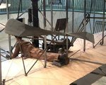
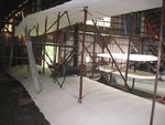
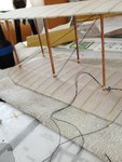
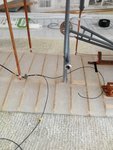
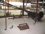
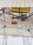
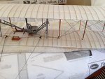
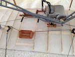
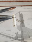
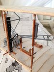
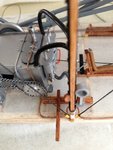
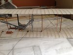
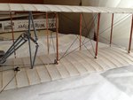
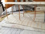
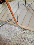
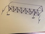
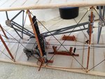
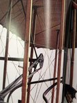
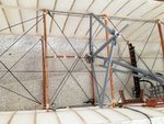
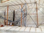
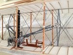
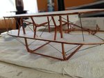
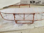
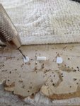
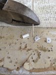
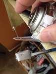
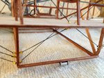
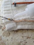
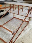
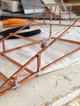
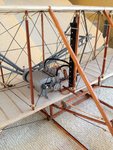
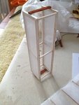
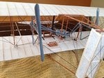
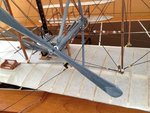
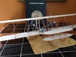
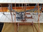
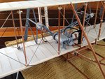
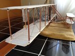
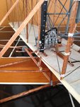
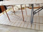
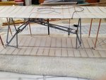
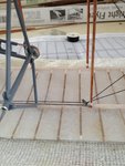
This may sound odd, but I decided to start with the rigging to the underside of the top wing. This rigging is very simplified and easy to do. I wanted the model to be ready for the more complex rigging of the lower wing along with the rudder and I felt to turn the model upside down while it is more detailed would risk damage. The following photos show the model upside down and the start of the rigging of wing warping. Notice the parallel rigging on the underside of the top wing for the two cables for the outer wing struts.
 

Attachments

  • IMG_2618.JPG
    IMG_2618.JPG
    838.4 KB · Views: 133
  • IMG_2621.JPG
    IMG_2621.JPG
    922.8 KB · Views: 134
  • IMG_2622.JPG
    IMG_2622.JPG
    904.7 KB · Views: 123
Last edited:
Going back to researching the plane, I can see how the lower wing is rigged in a manner that has the cables twisted before and also after the pulley. From these photos, it is not easy to see, as one will have to look carefully to notice the rigging and the twisting. For this, I decided to replicate it onto the model. I decided to flip the model right side up. However, occasionally, I find myself flipping the model both upside down and back to help with the rigging. I'm glad I didn't add the rudder or the elevators at this point. It also reinforces my statement made earlier, to leave out many items such as wing struts to allow me access to the inner workings of the model and to work from the inside out.
 

Attachments

  • 751.JPG
    751.JPG
    28.2 KB · Views: 130
  • 014.JPG
    014.JPG
    236 KB · Views: 134
  • IMG_2607.JPG
    IMG_2607.JPG
    926.8 KB · Views: 106
  • IMG_2604.JPG
    IMG_2604.JPG
    1 MB · Views: 128
Last edited:
Research has revealed that the Flyer has bellcranks to connect the wing warping system to the rudder. I also noticed that the pilot's cradle has leather as well as the lower portion of the wing struts have a light-colored thread wrapped around. I'm now adding the rigging through the pilot's foot rest and cradle as well as the bellcranks. The bellcranks will connect to the rudder after I'm finished rigging. The first picture shows the initial start of the rigging of the bellcranks and the connection to the pilot's cradle. It looks like a mess. Not to worry. It'll all come out really nice. As the next photos show, the threads are being pulled taut and everything is turning out very nice. I also took a close up of the rigging through the bellcranks and pilot's cradle. Notice how the rigging on the right side of the cradle goes under the engine, just like on the real 'Flyer. By this time, I have already assembled the radiator and completed plumbing from the radiator to the engine. I also added leather to the pilot's seat. At this stage, the rigging for wing warping is now complete. You can easily see how the lower and upper wings are connected through the "closed loop" system.
 

Attachments

  • 013.JPG
    013.JPG
    240 KB · Views: 121
  • IMG_2610.JPG
    IMG_2610.JPG
    969.6 KB · Views: 129
  • IMG_2627.JPG
    IMG_2627.JPG
    972.4 KB · Views: 161
  • IMG_2625.JPG
    IMG_2625.JPG
    843.4 KB · Views: 106
For the fuel tank, research revealed that the Wright Bros only had a very small tank of .44 gallons. Not even a half gallon! They obviously felt just to get their Flyer off the ground would be sufficient. To replicate this tank, I used a medium sized Evergreen Plastic tube that I guessed to be about the right size in diameter. Since the Wright Bros did not keep any drawings of their Flyer, The plastic tube was cut to length based upon the length I saw in the pictures. I then added some artistic license again and used some small rings that were purchased from a local arts and crafts store. I slipped the rings over the plastic tube and glued them into place. Next, I used some filler compound to fill up the bottom of the tank to a rough cone shape. When it was dry (about two hours later), it was sanded smooth and given a coat of primer and sanded again to smoothness. From there, I used a can of gray-colored spray paint. The plastic tank was given a "top" in the form of plastic that was cut to size from a sheet and glued in placed. The plastic top was given a "strap" by using a small strip of paper cut to length and glued in place. Then the whole tank was glued to the wing strut. Looks nice, eh?
 

Attachments

  • IMG_2581.JPG
    IMG_2581.JPG
    816.4 KB · Views: 78
  • IMG_2583.JPG
    IMG_2583.JPG
    817.1 KB · Views: 82
  • Wright Flyer reduced # 98.jpg
    Wright Flyer reduced # 98.jpg
    43.3 KB · Views: 80
  • IMG_2596.JPG
    IMG_2596.JPG
    743.3 KB · Views: 101
  • IMG_2603.JPG
    IMG_2603.JPG
    792.4 KB · Views: 93
Photos of the real Flyer shows the fuel line drooping from the engine, under the pilot and back up to the fuel tank. I didn't like this arrangement and decided to make the fuel line more rigid. This was the only time I altered the model from the original. As you can compare, the differences are very pronounced. I think it looked better this way. The last picture also shows the completed rigging. The fuel line was installed long before the rigging got to this stage.
 

Attachments

  • IMG_2005.JPG
    IMG_2005.JPG
    18.2 KB · Views: 90
  • IMG_2645.JPG
    IMG_2645.JPG
    1 MB · Views: 100
  • IMG_2635.JPG
    IMG_2635.JPG
    834.6 KB · Views: 176
With the rigging for wing warping complete and all of the accessories as the fuel tank, engine and radiator as well as the plumbing, pilot's cradle and magneto, it was now time to start the Longitudinal rigging between the front and rear wing struts. This is an area that is often overlooked by many modelers. It's the longitudinal rigging that really helps the ensure accuracy of the model as you can see from the blueprints on the last photo. For most of the rigging that needed to have the thread go through the wing struts, I used a needle that was slightly curved so I can avoid accidentally sticking the pointed end through the covering..

Finally, notice that the rear struts are still missing? Now that I have completed the initial detailing of the inner parts of the model, along with the rigging that requires my hands to gain access, I can finally glue the remaining struts into place.
 

Attachments

  • IMG_2629.JPG
    IMG_2629.JPG
    861.8 KB · Views: 162
  • IMG_2632.JPG
    IMG_2632.JPG
    927.2 KB · Views: 97
  • IMG_2631.JPG
    IMG_2631.JPG
    964 KB · Views: 119
  • IMG_2634.JPG
    IMG_2634.JPG
    909 KB · Views: 99
  • IMG_2120.JPG
    IMG_2120.JPG
    1.1 MB · Views: 135
Now I can start the rigging. I decided to lay out a plan first, to make sure I was accurate. Notice how I included the knot at the ends of the horizontal rigging.
 

Attachments

  • Wright Flyer reduced # 145.jpg
    Wright Flyer reduced # 145.jpg
    17 KB · Views: 86
  • Wright Flyer reduced # 144.jpg
    Wright Flyer reduced # 144.jpg
    17.8 KB · Views: 78
This is the start of the rigging for the front.
 

Attachments

  • IMG_2635.JPG
    IMG_2635.JPG
    834.6 KB · Views: 79
Research has shown that the horizontal rigging on the rear has long wooden poles tied on each side to help hold the rigging in place from the propellers. You can barely see the wooden poles just behind the pilot's head on the last picture. The photo of the blueprint accidentally cut off the words for the wooden poles but you can see the lines and arrow pointing to the area where they are to be installed. On the last two pictures, it's a photographic illusion but the wooden horizontal struts are actually in the front of these pictures.
 

Attachments

  • IMG_3500.JPG
    IMG_3500.JPG
    1.4 MB · Views: 99
  • Wright Flyer reduced # 57.jpg
    Wright Flyer reduced # 57.jpg
    51 KB · Views: 107
  • IMG_2652.JPG
    IMG_2652.JPG
    1.1 MB · Views: 100
  • IMG_2659.JPG
    IMG_2659.JPG
    1.1 MB · Views: 107
These two pictures show the front view and the rear view of the completed rigging. All this is before I installed the front elevators and the rear rudders.
 

Attachments

  • IMG_2658.JPG
    IMG_2658.JPG
    1.1 MB · Views: 130
  • IMG_2659.JPG
    IMG_2659.JPG
    1.1 MB · Views: 81
Thank you Wurger. I'm honored of your approval. I sent you an email that has photo attachments.
 
The front elevator assembly.
 

Attachments

  • IMG_2662.JPG
    IMG_2662.JPG
    798.8 KB · Views: 87
  • IMG_2666.JPG
    IMG_2666.JPG
    1,014.8 KB · Views: 93
The front elevator also had a small roller at the bottom of the skid. To this, I made out of scrap pieces of plastic cut to size and spray painted silver to simulate the metal. Next, I drove a pin through one of the small plastic tubing to be used as an axle..
 

Attachments

  • IMG_2667.JPG
    IMG_2667.JPG
    795.8 KB · Views: 78
  • IMG_2669.JPG
    IMG_2669.JPG
    866.2 KB · Views: 90
  • IMG_2672.JPG
    IMG_2672.JPG
    826.4 KB · Views: 98
  • IMG_2692.JPG
    IMG_2692.JPG
    1.2 MB · Views: 78
The front elevator assembly also required the pilot's control column along with the chains connected to the front elevators. The last picture shows I used small strips of paper painted silver to simulate the brackets used to hold the framework together.
 

Attachments

  • IMG_2673.JPG
    IMG_2673.JPG
    891 KB · Views: 67
  • IMG_2680.JPG
    IMG_2680.JPG
    989.2 KB · Views: 73
  • IMG_2681.JPG
    IMG_2681.JPG
    1 MB · Views: 98
The whole elevator assembly was then glued to the front end of the Flyer. You can easily see how the front elevators would get in my way of trying to rig the wings and install all of the accessories. This is what I mean about "working from the insdie out."
 

Attachments

  • IMG_2690.JPG
    IMG_2690.JPG
    1.5 MB · Views: 90
The rudders were completed and installed. The crossed over rigging was then connected from the bellcranks to the rudders. The propellers were then carved out, painted gray and trial-fitted. After the propellers were trial-fitted, they were removed and the tips were painted a lighter shade of gray to simulate the fabric tips.
 

Attachments

  • Wright Flyer reduced # 146.jpg
    Wright Flyer reduced # 146.jpg
    41.1 KB · Views: 88
  • Wright Flyer reduced # 147.jpg
    Wright Flyer reduced # 147.jpg
    59.4 KB · Views: 78
  • Wright Flyer reduced # 148.jpg
    Wright Flyer reduced # 148.jpg
    54.9 KB · Views: 83
There you have it. The completed model of the Wright Bros' Flyer. I hope you all enjoyed the show.
 

Attachments

  • Wright Flyer reduced # 86.jpg
    Wright Flyer reduced # 86.jpg
    51.1 KB · Views: 156
  • IMG_2705.JPG
    IMG_2705.JPG
    1 MB · Views: 201
  • IMG_2706.JPG
    IMG_2706.JPG
    1.1 MB · Views: 131
  • IMG_2725.JPG
    IMG_2725.JPG
    959.9 KB · Views: 105
  • IMG_2729.JPG
    IMG_2729.JPG
    1,019.6 KB · Views: 107

Users who are viewing this thread

Back