Navigation
Install the app
How to install the app on iOS
Follow along with the video below to see how to install our site as a web app on your home screen.
Note: This feature may not be available in some browsers.
More options
You are using an out of date browser. It may not display this or other websites correctly.
You should upgrade or use an alternative browser.
You should upgrade or use an alternative browser.
1:32 scale Lancaster Mk.1 Hachette Partworks
- Thread starter Gerry
- Start date
Ad: This forum contains affiliate links to products on Amazon and eBay. More information in Terms and rules
More options
Who Replied?N4521U
Plastic Pirate
Envy is written across the forehead of everyone looking in on this one.
DBII
Senior Master Sergeant
Nice looking bird.
DBII
DBII
Crimea_River
Marshal
David, you nailed that one! I'll put my money on those green thingies being the oxygen bags.
Catch22
Major
Wow.
- Thread starter
- #286
Gerry
Staff Sergeant
I'll give £30 delivery costs, a £1 tip, and a few beers !!
If that doesn't clinch it, I'll throw in a stunning 22 year old virgin as well.
And now you know I'm talking b*ll*cks, as finding even a virgin in my town is like discovering rocking horse poo, and stunning ? Only by the punch delivered by a newbie, trainee , light weight Hippocroccofrog, weighing in at a mere 200 Pounds - the slim variety !!!
Hmmm... Ian's offer suddenly sounds a lot more attractive...certainly not going there on my holidays, then!!
Thanks to all for posting, Terry, Darryl, David, Wurger, Bill, DBII, Andy Cory. Always good to hear from you.
David, thanks for posting that diagram. it's much more legible than the tiny jpeg I found. Ironically, I'm the proud owner of the Haynes Lancaster manual - on loan to a friend at the moment. I've no recollection of seeing that diagram and can't wait to get it back to see how I missed it. My wife often tells me I'm the most unobservant person she knows - hope she doesn't find out about this one!
 Gerry (I'm beginning to burnout this icon!)
Last edited:
vikingBerserker
Lieutenant General
My pleasure, it's on page 118. Being the "most unobservant person she knows" you certainly have an eye for incredible detail!
punjab pete
Recruit
- 2
- Jul 23, 2013
Thanks for the assist.
Peter.
Peter.
- Thread starter
- #289
Gerry
Staff Sergeant
Hi again,
We had my wife's cousin visiting from abroad for the past week so consequently the build suffered. And David, I got my Haynes Lancaster Manual back, and I can't believe how I missed the emergency equipment graphic - it takes up a full half page! Guess I was concentrating on the photo references (lame excuse).
I've had my first major SNAFU on the build. I was working on the S/Board wing inner trailing edge, which contains the dinghy stowage, before I was interrupted. I followed the instructions and it turned out fine, I thought.

Apart from sticking the edge of it (the green stain) to my cutting board, it went together very easily - until, that is, I lined it up against the main S/Board wing section and found the ribs don't line up as they do on the port wing.

I was kicking myself for getting it wrong until I checked the instructions carefully again and found the fault wasn't mine but the magazine's. This was something I hadn't picked up on in other builds and, so far, I haven't found that the magazine has ever corrected it in later issues.
This, I think, leaves me with two options, as I don't think I can unpick the assembly which was superglued. Option 1: I could disguise the error when I skin the wings by conforming the rivets and panel lines to follow the main wing section ribs or, Option 2: try to get another copy of that particular issue and build it correctly which can be done if the inner spar is reversed. This however, gives rise to another small problem. Because the ribs aren't evenly spaced the dinghy compartment will be approx. 2mm shorter on the width which might affect the equipment that's contained in it. As you can see, I haven't strung it yet in case I need to change it and that's something I want to talk about next.
I had, at first look, thought that the magazine had had got the proportion of the stowage compartment wrong. My impression, in most references that I've found, it that it is a square rather than a rectangular shape. However, on doing some research, I've found that both shapes appear to have been used. (See schematics below). I've highlighted the dinghy compartments in red for easier reference and tried to keep the same approx. magnification on both.


The top one is the one I'm most familiar with. This schematic is from the Haynes manual and is presumably from a contemporary RAF document. The second schematic is from the SAM Lancaster Modellers Datafile, in the fold-out endpapers (thanks, Terry). Unfortunately, neither are attributed with a Mark number. Despite some attempts to research dinghy stowage on the internet, there doesn't appear to be much information out there. What I'm trying to ascertain is; whether the compartments varied by Lancaster mark or by time, i.e. were larger dinghy compartments added to earlier marks as dinghy technology improved?
The final photo shows the dinghy equipment supplied for the build. (Issue 47 - a little bit down the line yet). Does this have any resemblance to the actual equipment? I have found some information on dinghy stowage on page 108 of the SAM guide. This seems to be for the 'square' compartment and seems to have a different layout, although it's difficult to be sure from the angle of the illustrations. Depending on what feedback I receive, I'll go with either the magazine route or, alternatively, try to modify to the squarer shape.

There's no rush on getting this sorted, as it can be completed further along in the sequence. My next build section contains the Camilla bunk and the portable oxygen bottles beneath and that's what I've started on now.
Keep you posted,
Gerry
We had my wife's cousin visiting from abroad for the past week so consequently the build suffered. And David, I got my Haynes Lancaster Manual back, and I can't believe how I missed the emergency equipment graphic - it takes up a full half page! Guess I was concentrating on the photo references (lame excuse).
I've had my first major SNAFU on the build. I was working on the S/Board wing inner trailing edge, which contains the dinghy stowage, before I was interrupted. I followed the instructions and it turned out fine, I thought.
Apart from sticking the edge of it (the green stain) to my cutting board, it went together very easily - until, that is, I lined it up against the main S/Board wing section and found the ribs don't line up as they do on the port wing.
I was kicking myself for getting it wrong until I checked the instructions carefully again and found the fault wasn't mine but the magazine's. This was something I hadn't picked up on in other builds and, so far, I haven't found that the magazine has ever corrected it in later issues.
This, I think, leaves me with two options, as I don't think I can unpick the assembly which was superglued. Option 1: I could disguise the error when I skin the wings by conforming the rivets and panel lines to follow the main wing section ribs or, Option 2: try to get another copy of that particular issue and build it correctly which can be done if the inner spar is reversed. This however, gives rise to another small problem. Because the ribs aren't evenly spaced the dinghy compartment will be approx. 2mm shorter on the width which might affect the equipment that's contained in it. As you can see, I haven't strung it yet in case I need to change it and that's something I want to talk about next.
I had, at first look, thought that the magazine had had got the proportion of the stowage compartment wrong. My impression, in most references that I've found, it that it is a square rather than a rectangular shape. However, on doing some research, I've found that both shapes appear to have been used. (See schematics below). I've highlighted the dinghy compartments in red for easier reference and tried to keep the same approx. magnification on both.
The top one is the one I'm most familiar with. This schematic is from the Haynes manual and is presumably from a contemporary RAF document. The second schematic is from the SAM Lancaster Modellers Datafile, in the fold-out endpapers (thanks, Terry). Unfortunately, neither are attributed with a Mark number. Despite some attempts to research dinghy stowage on the internet, there doesn't appear to be much information out there. What I'm trying to ascertain is; whether the compartments varied by Lancaster mark or by time, i.e. were larger dinghy compartments added to earlier marks as dinghy technology improved?
The final photo shows the dinghy equipment supplied for the build. (Issue 47 - a little bit down the line yet). Does this have any resemblance to the actual equipment? I have found some information on dinghy stowage on page 108 of the SAM guide. This seems to be for the 'square' compartment and seems to have a different layout, although it's difficult to be sure from the angle of the illustrations. Depending on what feedback I receive, I'll go with either the magazine route or, alternatively, try to modify to the squarer shape.
There's no rush on getting this sorted, as it can be completed further along in the sequence. My next build section contains the Camilla bunk and the portable oxygen bottles beneath and that's what I've started on now.
Keep you posted,
Gerry
vikingBerserker
Lieutenant General
This has been one of the most amazing builds I've ever seen. Kudos to you!
- Thread starter
- #291
Gerry
Staff Sergeant
Thanks David and Peter.
Looks great so far Gerry!
meatloaf109
1st Lieutenant
I agree!This has been one of the most amazing builds I've ever seen. Kudos to you!
Airframes
Benevolens Magister
I think I'd go with your Option 1, and just re-scribe panel lines/rivets as required. It'll save a lot of extra work, and possible damage and, after all, once it's skinned the mis-aligned ribs won't be seen.
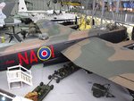
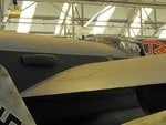
As for the dinghy stowage, it's not something I've really noticed before, and had thought that they were all square, although of course it's not always clear in photos, or viewing the real thing on the ground. An AVRO drawing I have certainly shows it as square, and it looks square in these two photos, one of the late-model Lanc at Duxford, the other the Cosford Lincoln. I've only ever seen the dinghy inflated, so can't help with the contents or arrangement of the stowage compartment. Again, I think I'd just go with the kit parts, for simplicity and ease of construction, but if you really need further details, then maybe a letter to the BBMF, or the Lincolnshire Aviation Heritage Center at East Kirby might provide some info?
EDIT: Darn! The Lanc pick has lost detail when posted on the forum! My original photo does show the hatch, and it looks square.
Attachments
Last edited:
- Thread starter
- #295
Gerry
Staff Sergeant
Thanks, Gnomey, Meatloaf and Terry.
Terry, I'm reassured by your comments. I didn't want to do something that would be totally wrong, but it would be easier to install the kit parts. Unless I get further info that would totally discredit this approach, that's what I'll do.
Cheers,
Gerry
Terry, I'm reassured by your comments. I didn't want to do something that would be totally wrong, but it would be easier to install the kit parts. Unless I get further info that would totally discredit this approach, that's what I'll do.
Cheers,
Gerry
ian lanc
Staff Sergeant
The Lanc' at EK isn't a square hole but more rectangle.
Picture taken by the official photographer at EK.

Picture taken by the official photographer at EK.
Last edited:
- Thread starter
- #297
Gerry
Staff Sergeant
Thanks Ian. That's more useful information that'll help me arrive at a reasoned decision.
Gerry
GerryAirframes
Benevolens Magister
I've just had another look at photos and drawings. The AVRO drawing I mentioned is actually the same drawing as your first example posted Gerry, and I believe it is an early example, based on the original Manchester drawing.
I've examined the original photo I took of the Duxford Lanc, and the Cosford Lincoln, as well as a couple of my slides of the BBMF Lanc and, on closer inspection, they all look more like East Kirby's Lanc, as posted by Ian - that is, more rectangular than square. I've also checked some wartime shots of early Lancs, and it would seem that early production airframes, probably utilising original Manchester components, had a 'square' hatch, with later examples having a slightly enlarged, rectangular hatch. Presumably, this was to accommodate an improved, larger dinghy and equipment.
Note that the proportions are more like those in your kit, as opposed to your second drawing, with the hatch being only 'slightly' rectangular. Note also that the hatch outline was marked in Dull Red, the same as the code letters, and not the brighter red as seen on the EK Lanc.
Lucky13
Forum Mascot
Thanks Ian. That's more useful information that'll help me arrive at a reasoned decision.
Don't one need a, or several, beers to come to reasoned and logical decision, solution??
Airframes
Benevolens Magister
That's when the decision is made to have more beer!
Gerry, I don't know how I missed this, but have another look at the AVRO drawing, and then compare this to the kit parts.
In the drawing, the wing ribs are numbered, and the dinghy compartment is the width of three ribs, this being based on the original Manchester design (and the Manchester had a crew of 6, or 7 depending on role.).
The kit, on the other hand, shows the compartment being the width of four ribs and, bearing in mind the Lancaster's official crew numbered 7, one more than previous types (when the 'Special Operator' [for ABC and some other equipment] was included, the crew was eight), this would require a larger dinghy than originally carried, along with extra canned water and food rations, then it makes sense that the dinghy compartment was enlarged to accommodate this equipment, the modification being carried out in the most convenient way, by simply extending by one rib space.
The original dinghy carried would be standard equipment, as designed for the largest bombers of the period up to the introduction of the four-engined types, that is, Wellington, Whitley and Hampden, where the maximum crew would not normally exceed six. So, with a newer, larger dinghy being needed, a larger compartment was also required !
Last edited:
Users who are viewing this thread
Total: 1 (members: 0, guests: 1)