1/32nd Scale 'Revegawa' Spitfire MkXIVc

Ad: This forum contains affiliate links to products on Amazon and eBay. More information in Terms and rules

Wojtek, maybe if we started with an Albatross and a Sopwith Camel, we could end up with a Bf109E !?!!


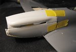
It is possible some of Miliput epoxy putty here and there and ....the Bf109E appears.:lol:
 
I've finally got some 'normal' construction done, staring with the cockpit, but first I had to do a tiny bit more destruction, and cut out the aperture for the retractable tail whell, which will be fitted later, using the Mk.22 parts, as the Hasegaw kit provides the earlier, fixed, castoring tail wheel.
PIC 1 [/B ]Shows the hole cut to shape, awaiting sanding. Part of the original location point for the MkVI tail wheel has been left in place, and adapted to mount the Mk.22 wheel. The bay doors will be fitted near the end of the build.
PIC 2 Shows the cockpit frames, with the moulded-in lightening holes drilled out, and the padded headrest of the MKVI removed from the armour plate, and the area sanded smooth. Both frames have been painted Cockpit Green.
PIC 3. The kit instrument panel is really rather good, with moulded-in detail, and this has been painted, and the instrument dials glazed with clear varnish. It's not 100% accurate for the MkXIV, but to be honest, you'd have to squint into the cockpit and still be hard pressed to tell the difference between the two! A scrath-built Mk.II gyro gunsight will be added later.
PIC 4. [/B ]The seat frame and seat have been assembled and painted, and again, considering the age of this kit, these are rather nicely produced items. It's no wonder that Hasegawa won a reputation for fine detail, although the seat itself is not totally accurate. The seat on the real aircraft was made from a laminate of papier mache and resin, hence the colour, and did not always have the padded back cushion fitted. However, there should be a small well in the centre of the seat pan, which was designed to house the parachute pack closure pouch, in order that the ripcord pins didn't get bent by the pilot's weight bearing down on the pack - this would prove fatal if the parachute had to be used in an emergency! There should also be a small recess, moulded into the port seat pan wall, to allow the bulkier parachute harness waist webbing, which held the ripcord, ripcord 'D' ring handle and the quick-release box, to fit without fouling or kinking the Bowden cable of the rip cord. I'm not complaining though, as considering this kit (as a Mk.V) was first released in the early '70's, the finesse of the seat moulding is outstanding, and was way ahead of anything else at the time.
The Sutton harness was made from strips of fairly thick foil, cut from the packaging my pain killers come in (!), which was then punched with a needle to simulate the fastening/adjusting eyelets, and painted. The adjusters were made from small strips of the same material, whilst the release pin and tail-strap attachment cable were made from stretched sprue. The fastening lug, a circular 'buckle' similar in appearance to a parachute harness quick-release box, has been made from a mould ejection tab, but had yet to be fitted to the starboard lap-strap when the photos were taken.
PICS 5 and 6. The kit parts for the cockpit walls are moulded as separate items, including curved lower 'walls', to simulate the curve of the fuselage for the floor-less cockpit. I just painted these, and added a couple of scratch-built items, such as the oxygen hose, the spare bulb rack for the reflector sight, and a couple of placards here and there. The latter were made by painting some self-adhesive silver foil matt black, cutting to size and positioning in the required place. When they were firmly stuck down, the matt black paint was 'picked' with a pin, to simulate the engraved or stamped lettering etc on the bare metal.
PICS 7 and 8 A couple of shots of the main cockpit components assembled. The only addition here is the parking brake lever added to the control column grip, made from stretched sprue.
PICS 9 and 10 Show the cockpit in place on the starboard wall, with the harness attachment cable running back to a point in the mid fuselage.
That's it so far. Once the cockpit has fully set, a plastic card fillet will be glued onto the inside of the modified fin, and the fuselage halves will be joined. When this has totally set, work will begin on the fin fillet, which will be profiled and blended in with Milliput, and the Mk.22 rudder added, after cutting and sanding to match the profile of the MkXIV broad-chord rudder.
Thanks again for your interest and kind comments.
 

Attachments

  • Spit XIV Build 081.jpg
    Spit XIV Build 081.jpg
    31.9 KB · Views: 156
  • Spit XIV Build 087.jpg
    Spit XIV Build 087.jpg
    29.7 KB · Views: 156
  • Spit XIV Build 091.jpg
    Spit XIV Build 091.jpg
    43.3 KB · Views: 156
  • Spit XIV Build 095.jpg
    Spit XIV Build 095.jpg
    31.4 KB · Views: 153
  • Spit XIV Build 099.jpg
    Spit XIV Build 099.jpg
    41.2 KB · Views: 150
  • Spit XIV Build 111.jpg
    Spit XIV Build 111.jpg
    39.7 KB · Views: 154
  • Spit XIV Build 108.jpg
    Spit XIV Build 108.jpg
    40.9 KB · Views: 152
  • Spit XIV Build 103.jpg
    Spit XIV Build 103.jpg
    35.3 KB · Views: 151
  • Spit XIV Build 101.jpg
    Spit XIV Build 101.jpg
    36.1 KB · Views: 165
  • Spit XIV Build 098.jpg
    Spit XIV Build 098.jpg
    36.2 KB · Views: 162
Thanks very much, Cory and Karl, and Wojtek, I'll be there as soon as possible!
I'll make a separate post in the Questions threads, as I now have a slight problem........
 
Thanks again guys, it's very much appreciated!
Got quite a bit more done, and it's starting to look more like a Spitfire, rather than the remains in a butcher's shop!
The fuselage has been joined and glued, with the exception of the fin, which has been left in order to insert the plastic card fillet for the new, wider-chord fin.
PICS 1 and 2 are general shots into the cockpit, and I'm afraid I goofed, as I had the camera on 'Auto', instead of 'Aperture Priority, hence the slightly out of focus pics!
PIC 3. To profile the new rudder and fin, the 1/32nd scale plan was traced, and the shape of the new rudder transfered to the Mk22 rudder, which has been marked in blue where the plastic needs to be removed. The original Mk.V rudder is on the right.
PIC 4 shows the fin extension cut from .75mm plastic card, to be inserted into the modified fin, then glued. The blue line is a datum for the leading edge of the existing fin, to aid in alignment.
PIC 5. The extension fillet is glued in place, and a 'cap' has been added to the top of the fin, to allow the correct profile to obtained with the rudder. The 'cap' has yet to be trimmed and sanded, and the fillet will be blended in to the fin with Milliput epoxy putty.
PIC 6. Is the rudder trim tab and actuator on the Mk.22 rudder. The tab needs to be modified, to remove the offset 'step', and the actuator removed and replaced with a scratch-built item.
PIC 7. Shows the new rudder, modified from the Mk.22 kit parts, with the original Mk.V item for comparison. The 'taped' ribs were made by cutting very shallow slots into the rudder surface, then laying in thin strands of stretched sprue, which were then sanded when the cement had fully set. The leading edge 'stitching' was engraved using the point of a scalpel blade, and the base for the tail lamp has been added, from shaped pieces of stretched sprue, and will be contoured later. Note the whole lot, including the trim tab insert, has yet to be cleaned up.
PIC 8 is the new trim tab actuator, which will be enhanced slightly later.
PIC 9 Shows the first test fit of the new rudder, checking alignment.
PIC 10. This is the hard part, and the most critical! The firewall has been fitted, made from .75mm plastic card, reinforced by bracing strips inside the fuselage. The blue 'bar' is a length of .5mm thick plastic strip, providing reinforcement between the vertical and angled parts of the firewall, and the two white pieces across the lower gap are to provide bracing, and a backing for the lower cowling from the Mk.22. The edges have yet to be trimmed and sanded, to provide a ledge onto which the upper and side cowlings will sit. The red squares are the locating points for the engine bearers. A small pilot hole will be drilled in each square, and the bearers test fitted for alignment. Once I'm happy that the bearers are in the correct position, further alignment will take place, with the engine in position, before proper locating holes are drilled for the bearers, which will then be cemented in place, and reinforced with superglued 'brackets' around the sides and bottom edges.
PIC 11 shows the lower cowling test fitted, held in place on the underside with tape. This will be adjusted as required, before being aligned with the engine lower surface, and the engine bearers.
PIC 12. In order to check the overall geometry of the nose, the port side and top cowlings have been taped in place. So far, the fit looks reasonable, with a minimal amount of internal 'plating' and some filling being required around the wing root joint. Note, the the oversize cowling fateners will be removed, and new ones engraved.
So, that's it so far. I'm begining to think that this will work out quite well, but I'm not counting any chickens yet, as I remember having a few problems with the engine and nose alignment the last time I did this conversion.
The more I do on this, and the 'derelict' Mk.22, the more I fancy doing a Mk.21, and then using the 'left overs' to build a low-back LF16E - that's if the Hasegawa kits are still available when, or if, I eventually get around to it, as the Mk.V appears to be now out of circulation, and the MkVI lacks some useful parts that are included in the Mk.V. Still, that's something for the future!
Thanks again for your kind comments, and I'll post some more progress shots soon.
 

Attachments

  • Spit XIV Build 136.jpg
    Spit XIV Build 136.jpg
    32.3 KB · Views: 132
  • Spit XIV Build 124.jpg
    Spit XIV Build 124.jpg
    56.8 KB · Views: 126
  • Spit XIV Build 113.jpg
    Spit XIV Build 113.jpg
    34.2 KB · Views: 127
  • Spit XIV Build 121.jpg
    Spit XIV Build 121.jpg
    42.8 KB · Views: 128
  • Spit XIV Build 114.jpg
    Spit XIV Build 114.jpg
    48.5 KB · Views: 130
  • Spit XIV Build 129.jpg
    Spit XIV Build 129.jpg
    48.2 KB · Views: 129
  • Spit XIV Build 134.jpg
    Spit XIV Build 134.jpg
    71.3 KB · Views: 127
  • Spit XIV Build 133.jpg
    Spit XIV Build 133.jpg
    72.1 KB · Views: 129
  • Spit XIV Build 132.jpg
    Spit XIV Build 132.jpg
    32.1 KB · Views: 125
  • Spit XIV Build 140.jpg
    Spit XIV Build 140.jpg
    31.1 KB · Views: 133
  • Spit XIV Build 141.jpg
    Spit XIV Build 141.jpg
    49.1 KB · Views: 127
  • Spit XIV Build 142.jpg
    Spit XIV Build 142.jpg
    30.6 KB · Views: 134

Users who are viewing this thread

Back