- Thread starter
- #41
Airframes
Benevolens Magister
Get to it Evan! I've found even more slides of the PR19 for you, that is, if some shots of it stripped down for deep service, lacking its engine, are of any use?! I'm hoping to get them (and many more interesting pics) scanned fairly soon.
Well, the destruction stages are nearly finished, only some small areas to attend to, before some construction can begin, at last! I was begining to think there would be very little plastic left, especially on the wings, which have now lost a lot of their rigidity due to all the extra ventilation!
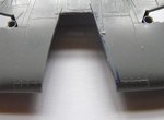
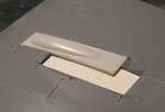
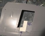
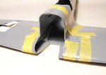
PIC 1.Shows the recess cut from the MkVI forward centre-section, slightly oversize, to allow some room to position and fit the new, longer lower cowling from the Mk.22.
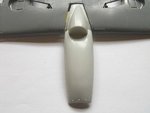
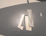
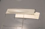
PIC 2.Shows this item test-fitted, taped in place. A backing strip will be glued inside the centre-section, to support the cowling, which will be glued in place, and then the gaps filled with plastic strip, and filled, before sanding smooth and blending into the surroundings.
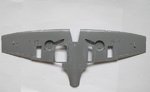
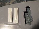
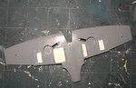
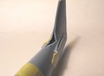
PIC 3. This is the bottom wing, after the removal of the radiator, oil cooler and the lower cannon blisters. These areas will be blanked-off with plastic card and filler, and then the Mk.22 radiators will be fitted, along with some home-produced, small cannon blisters, which will be moulded from thin plastic sheet. I need to check to see if the gun heating exit ducts, near the wing tips, should be removed, as I don't think these were present on the Mk.XIV. If not, then it's more cutting and filling!
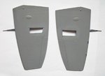
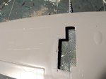
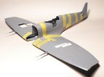
PIC 4. Shows the wing tops, with the cannon blisters of the 'B' wing removed. The port wing will have the opening filled, and another hole cut to take a modified gun cover and blister, from the Mk.22, to represent the 'C' wing of the Mk.XIV. The ammunition hatch for the cannon will then be scribed, and the hatches for the .303 MG's will be lightly scribed over the current raised detail.
I hope to be able to utilise one of the Hispano cannons from the Mk.22 kit, and fit this into the starboard wing, in which case the wing will undego further surgery, to open-up the gun and ammo bay, then the same procedure of filling and scribing will be followed. I've got a couple or six spare .50 cal Brownings, so I'm toying with the idea of fitting one of these alongside the cannon, although these were rarely, if ever, fitted into the 'C' wing, being more common on the 'E' wing, which then omitted the .303 guns. As I've more or less settled on a colour scheme representing an earlier Mk.XIVc, I'll have to give this some thought before proceeding.
Apart from some minor surgery to construct the retractable tail-whell of the Mk.XIV, and a few other small areas, the major 'destruction' is virtually complete, and I can proceed with the construction, following the steps in the Hasegawa instructions, apart from some scratch-built detailing additions. Once the interior parts have been painted and assembled, and the fuselage and wing joined, then the critical part begins. This will be the alignment and fitting of the engine, onto the scratch-built firewall, which has to be absolutely accurate in order to allow the cowlings to fit, and the prop and spinner to line up. I'm aiming to display the starboard side of the engine, which will allow a little leeway for aligning the cowlings but, of course, this could all go to rat poo!
Thanks again for your interest,
Terry.
Well, the destruction stages are nearly finished, only some small areas to attend to, before some construction can begin, at last! I was begining to think there would be very little plastic left, especially on the wings, which have now lost a lot of their rigidity due to all the extra ventilation!
PIC 1.Shows the recess cut from the MkVI forward centre-section, slightly oversize, to allow some room to position and fit the new, longer lower cowling from the Mk.22.
PIC 2.Shows this item test-fitted, taped in place. A backing strip will be glued inside the centre-section, to support the cowling, which will be glued in place, and then the gaps filled with plastic strip, and filled, before sanding smooth and blending into the surroundings.
PIC 3. This is the bottom wing, after the removal of the radiator, oil cooler and the lower cannon blisters. These areas will be blanked-off with plastic card and filler, and then the Mk.22 radiators will be fitted, along with some home-produced, small cannon blisters, which will be moulded from thin plastic sheet. I need to check to see if the gun heating exit ducts, near the wing tips, should be removed, as I don't think these were present on the Mk.XIV. If not, then it's more cutting and filling!
PIC 4. Shows the wing tops, with the cannon blisters of the 'B' wing removed. The port wing will have the opening filled, and another hole cut to take a modified gun cover and blister, from the Mk.22, to represent the 'C' wing of the Mk.XIV. The ammunition hatch for the cannon will then be scribed, and the hatches for the .303 MG's will be lightly scribed over the current raised detail.
I hope to be able to utilise one of the Hispano cannons from the Mk.22 kit, and fit this into the starboard wing, in which case the wing will undego further surgery, to open-up the gun and ammo bay, then the same procedure of filling and scribing will be followed. I've got a couple or six spare .50 cal Brownings, so I'm toying with the idea of fitting one of these alongside the cannon, although these were rarely, if ever, fitted into the 'C' wing, being more common on the 'E' wing, which then omitted the .303 guns. As I've more or less settled on a colour scheme representing an earlier Mk.XIVc, I'll have to give this some thought before proceeding.
Apart from some minor surgery to construct the retractable tail-whell of the Mk.XIV, and a few other small areas, the major 'destruction' is virtually complete, and I can proceed with the construction, following the steps in the Hasegawa instructions, apart from some scratch-built detailing additions. Once the interior parts have been painted and assembled, and the fuselage and wing joined, then the critical part begins. This will be the alignment and fitting of the engine, onto the scratch-built firewall, which has to be absolutely accurate in order to allow the cowlings to fit, and the prop and spinner to line up. I'm aiming to display the starboard side of the engine, which will allow a little leeway for aligning the cowlings but, of course, this could all go to rat poo!
Thanks again for your interest,
Terry.