1/48 Spitfire Mk. XVI e - Home Country Modern Aircraft/Spitfire Marks GB

Ad: This forum contains affiliate links to products on Amazon and eBay. More information in Terms and rules
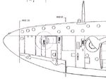
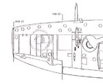
I have a question. On the underside of the wings. I have cut the 50 cal shell casing slots (2) one on each side but is the 20mm shell casing slot as large as the rectangle would indicate or is it smaller.
 
I'd need to see a pic of the moulded slot Aaron, but yes, the ejector port for the 20mm was a lot bigger than the .50 cal slot, the empty case being nearly twice as long, and of course much larger diameter around the base rim.
 
Here's a scale drawing of a Mk IX wing. XVI is the same I think. I believe the MG chutes also ejected the belt clips along with the spent cartridges through an elongated opening.
 

Attachments

  • Spitfire F IX C Wing.jpg
    Spitfire F IX C Wing.jpg
    58.3 KB · Views: 157
Thank you guys! Now I can finish out the wing detail.:thumbleft: :cool:
Well that's screwed up. My 20mm assemblies are reversed from those in your diagram Andy but the ejection chutes are identical. Are my instructions wrong?
 
Last edited:
No. The C wing on the Spit was built for two cannon side by side and it's possible to have the outer cannon installed and not the inner. Both configurations are possible.

EDIT: I've also attached a wing plan of a clipped wing Spitfire LF XVI but with no MG's. It has the outer cannons and you can see the ejector chute configuration on this one as well. This one has the bomb attachment point so may feature a different pattern here. Sorry to confuse and maybe Terry will comment/correct me.
 

Attachments

  • 215513.jpg
    215513.jpg
    38 KB · Views: 98
  • Spitfire LF XVI E Wing.jpg
    Spitfire LF XVI E Wing.jpg
    58.6 KB · Views: 5,951
Last edited:
Would have said that was an E wing myself Andy.
AFAIK the C wing only had inboard cannon but a choice of elongated or humped blisters depending on ammo drums fitted. Will be keen to see what Terry has to say on that.

Nice work so far Aaron!
 
The 'E' wing shown, has the cannon outboard, and a .50 cal inboard. The previous drawing shows the 'C' wing, with the cannon inboard, and an empty bay outboard, with the cannon mounting tube faired over with a rounded stub fairing. If the .50 cals were mounted, then these were inboard, if not, then the cannon was mounted outboard. Both wings used belt fed cannon, with a BFM (Belt Feed Mechanism) under the bulge - drum magazines were replaced after the 'B', with belt feed.
On the 'C' wing, with .303 Brownings, the empty cases and links were ejected through a common ejector port, with the 'notch' one one side being from the ejector port for the links on the side of the weapon, whilst the empty cases were ejected from the bottom of the weapon, the ejection port being directly above the elongated slot on the wing.
On the 'E' wing, the cannon cases are ejected from the longer slot, to the left and rear of the bomb pylon, with the links being ejected from the smaller slot to the right.
Immediately inboard of the pylon is the ejector slot for the .50 cal cases, with, to the left (outboard), a notch in the base of the pylon, where the slot for the links is located.
Note that only the black-shaded areas in the drawings are the actual opening, the other lines being the edges of the access panels.
Hope this helps.
 
:notworthy: Thank you VERY much guys!:notworthy: There are no guide lines on the inner inner ejection ports to indicate where to cut them out. Hince my confusion. I will just scribe the line and cut them out as best I can and keep going. I have dry fitted the main wing assembly and if I am patient and take my time when I glue it in there will be no need for filler, anywhere along the seem. Looking at this kit going together I keep thinking it is 1/72 because it is so small. This is the first Spitfire I have ever built so I never realized how small they actually were. Thanks again and I will try to post some progress shots tonight.:thumbright:
 
Cheers Andy and Terry!

Just to clarify Terry:
- C wings could or did as standard practice have the cannon mounted outboard if .50 cal MGs were not installed?
- the bulges were dictated by two different belt feed mechanisms, not one by a BFM the other by drum type ammo?
- If .50 cals were not fitted, were these manufactured sans ejector chutes and openings, or faired over?

If the first point is correct, it would help clarify a matter I have with a 485 (NZ) sqn bird (ML407, OU-V), recorded as both an LF.Mk.IXc and IXe, depending on source.
 
Evan, 'C' wing, no .50 cal, cannon mounted inboard, faired stub housing outboard. Wing bulges longer and slimmer on the 'E' wing, broader and higher on the 'C' wing. (Those on the Vb were shorter, and mounted further aft, as this covered a drum magazine.) The 'C' wing could also be seen with a much broader, flatter bulge, designed to cover the BFMs for two cannon, but this was mainly employed on the MkVc.
Wings were made with ejector port openings, but plated over as required depending on armament fit.
Spitfire ML407 was (and is) a MkIXc, (referred to during the war as a MkIXB) and had the cannon mounted inboard. This was the personal aircraft of Johhny Houlton, of 485 Sqn, and the history of this aircraft, along with some pics, is shown in his book 'Spitfire Strikes' (a great read, got it on my shelves).
This aircraft was restored to flying condition, and to two-seat configuration, by the late Nick Grace, and is operated today by his widow, Caroline Grace, and still caries the 'OU-V' codes. Johhny Houlton got to fly in his old mount during a visit to the UK in the 1990s.
The book is worth reading if you can get a copy Evan. Covers some good stuff, including his part in the development of the Gyro Gun Sight, which he'd been using from 1943, long before Britain passed details to the USA for the production of their K-14.
 
Cheers Terry!
And realised I got my wires crossed. I thought you meant the outboard Mgs were also removed, which didn't fit in with photos of RAAF VIIIc's which had standard C wing cannon, long slim bulges and out board MGs.

Suspected ML407 was a -C from her fit out too, a normally accurate site listing her as an -E which had me wondering what was going on!
Plan to model her in full D-day markings, so will try and read that book and find period photos for accuracy with the scheme.

Cheers again!
 
I'll scan amd e-mail all the relevant pics in the book Evan, along with a shot of the whole Squadron in the UK. The MkIX I converted from the Hasegawa 1/32nd scale MkV 25 years ago, has OU-P as it's markings - would have been OU-V if I'd had the book then!
 
Cheers Terry! Got the e-mail!
Great photos and info - only seen the squadron line up shot before, the rest are new to me!

And great model too - I think you should put it up in the 'Post your models' thread if you haven't already.

Cheers again!
 
I think it was shown in my old thread '30 years of Airframes' models' or something similar. Many of these are getting spoilt through being exposed to dust and nicotine - I really should invest in some glass cabinets!
 
Since I have had to switch to IE I can't work my photos. It will take some time to get this figured out. Sorry guys. I will continue to keep working on the model and taking photos and but photo updates will be none existent until I get this figured out.
 

Users who are viewing this thread

Back