Navigation
Install the app
How to install the app on iOS
Follow along with the video below to see how to install our site as a web app on your home screen.
Note: This feature may not be available in some browsers.
More options
You are using an out of date browser. It may not display this or other websites correctly.
You should upgrade or use an alternative browser.
You should upgrade or use an alternative browser.
**** DONE: 1/48 Bf-110 G-4 - Night War of WWII
Ad: This forum contains affiliate links to products on Amazon and eBay. More information in Terms and rules
More options
Who Replied?- Thread starter
- #82
Jeff Hunt
1st Lieutenant
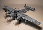
Finally found some bench time late yesterday afternoon and added various bits and bobs. Exhaust system, undercarriage doors, props and spinners and the first 2 of 4 radar aerials.
I glued the props in place as opposed to heating a blade and flattening the little plastic nipples so that the props could spin. She isn't a toy to be played with so I am not overly concerned about rotating blades.
Still a bit more to do but she will have to wait as I am going to visit my mother today to continue with the never ending Christmas of 2015!
Hope you all had a great Christmas.
Cheers,
Jeff
Airframes
Benevolens Magister
It's looking good Jeff.
Just one thing before you continue though - the antennae should be angled outward approximately 45 degrees, opposite to the way you have the first set, as shown on my model.
Hope you enjoy the rest of the Christmas break without too much hassle or interruption !
Just one thing before you continue though - the antennae should be angled outward approximately 45 degrees, opposite to the way you have the first set, as shown on my model.
Hope you enjoy the rest of the Christmas break without too much hassle or interruption !
Attachments
Crimea_River
Marshal
Not necessarily. The antennae were often vertically oriented but could also be slanted as you've shown.

Looking good so far Jeff!
Done good Jeff!
Nicely done Jeff
JKim
Senior Master Sergeant
Looks great Jeff! Nice clean finish!
Airframes
Benevolens Magister
Nice pic Andy. I'll admit, I don't think I've seen a pic of the antenna in the vertical position before now. I seem to remember reading (can't remember where) that the dipoles were angled to improve reception on one, possibly both, of the screens.
Crimea_River
Marshal
Nice pic Andy. I'll admit, I don't think I've seen a pic of the antenna in the vertical position before now. I seem to remember reading (can't remember where) that the dipoles were angled to improve reception on one, possibly both, of the screens.
Funny as almost all I've seen on the 110 are vertical. The 110 at Hendon has them vertical as well though the lower ones are slightly toed in:
A couple more period pics:
Airframes
Benevolens Magister
Since my last post, I found a couple more pics, including the one you posted, showing the vertical dipoles. But, the majority are angled, and are shown like this on scale plans I have.
Note that your second pic is the earlier set-up, with the central antenna also, and this was vertical. The third pic, I think they may be angled, and the RAFM example not quite accurate. I have read that, when it was refurbished and moved from St.Athan to Hendon, apart from the slightly incorrect re-paint, the antenna were incorrectly re-assembled.
The final pic I thought was the RAFM example in its original paint finish - but it appears to have the early, central antenna as well as the large 'antlers', so again, a slightly different set-up.
I'd need to find the info, but, as previously mentioned, I think the change of angle was to improve reception.
Good work Jeff!
Users who are viewing this thread
Total: 1 (members: 0, guests: 1)


