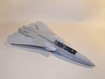
**** DONE: 1/48 Tornado F3 - Home Country Modern Aircraft / Spitfire Mark GB

Ad: This forum contains affiliate links to products on Amazon and eBay. More information in Terms and rules

Thanks very much, Hugh and Glenn. This one might be familiar to you Hugh, as it was based at Leuchars before the Squadron was disbanded as a fighter squadron and re-formed in the ECM role with Boeing Sentries.
Glenn, I'm happy to say that it's nowhere near as bad as the Buccaneer, as far as the joint goes, but I'll admit, I expected it to be worse than it turned out.
I've now got the joint fully sorted, apart from some minor polishing here and there, and it is actually better than it looks in the photos - the different coloured and textured plastics make things appear differently. A couple of hours work with the power tool, files, and wet n' dry got the joint as smooth as a baby's bum, and it's now ready to have the access panels engraved.
First though, the air intakes need to be altered and fitted, and I was right in expecting some work here. Test-fitting shows that some sanding, probably some shims, and a little filler will be needed to get the intakes aligned and seated properly, and the intakes themselves need some work, not only to correct some areas, but also to get the splitter plates to fit snugly and without gaps!
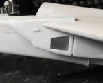
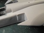
PICS 1 and 2 Show the fuselage joint now fitting snugly. The odd small scratches will be erased after the panels are engraved. The latter were very poorly defined on the top half, and shown as raised lines, not all matching, or in the correct place, on the lower half !
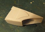
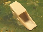
PIC 3. One of the air intake outer halves, showing the moulded nav lamp and the incorrectly positioned, and wrong sized, suction relief door. I've decided to pose the front doors slightly open, to detract from the otherwise plain appearance of the fuselage, so work has started to get this done, before fitting the intakes.
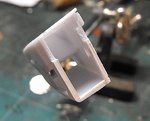
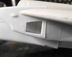
PIC 4. The front section of the 'lamp' has been removed, leaving the remainder as the fairing, and a transparent part will be made and fitted later. The relief door has been scribed in the correct place, and the right size, and is shown here being cut out. The door cover will be made from thin plastic card.
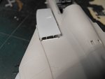
PIC 5. A comparison showing the 'new' door opening, next to the original part.
Once the intakes have been assembled, filled as required, and painted internally, they will be fitted to the fuselage, with copious amounts of plastic shims, filler and, no doubt, a variety of new swear words!
Thanks for your continued interest and compliments, and I hope to have more to show tomorrow.
 

Attachments

  • Tornado GB 114.jpg
    Tornado GB 114.jpg
    32.7 KB · Views: 75
  • Tornado GB 115.jpg
    Tornado GB 115.jpg
    32.8 KB · Views: 80
  • Tornado GB 116.jpg
    Tornado GB 116.jpg
    24.6 KB · Views: 80
  • Tornado GB 118.jpg
    Tornado GB 118.jpg
    46.3 KB · Views: 80
  • Tornado GB 119.jpg
    Tornado GB 119.jpg
    35.5 KB · Views: 79
Thanks guys - and one is quite enough I think!
Nearly got the intakes looking something like they should, although still quite a bit of filing and tidying to do.The root of the problem lies in the wing root! The mis-match of the top and bottom halves is so bad, that nothing lines up properly, causing gaps and steps, so some radical sanding and cutting has had to be done.
PIC 1 Shows the gap in this test fit.
PIC 2. First stage of correction is to sand back the wing root area.
PIC 3. The intakes still wouldn't seat correctly, so the boundary layer separator was filed down considerably.
PIC 4.. More test fitting showed that there would still be a large gap, so plastic card shims were added to the rear of the intake, and sanded roughly to shape.
PIC 5. Whilst at it, the inner rim of the intakes were chamfered, to get them looking more like the real thing.
PIC 6. With this all done, and the suction relief doors made and fitted, the port intake was finally glued in place. Once fully set, the joint will be sanded flush, and filler added as and where required - which is virtually everywhere!
PIC 7. Fins were also added to the bleed exits on the top rear of each intake duct, using stretched sprue.
PIC 8. Both intakes in place at last, the starboard side being slightly less hassle than the port. Both intakes will need some careful sanding, after filling the small gaps in various places.
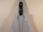
PIC 9. How the model looks so far - getting there. Next step is to fit the speed brakes and the fin, and scratch-build the reverse thrust bucket gears and actuators, not even hinted at in the kit.
More hopefully tomorrow.
 

Attachments

  • Tornado GB 124.jpg
    Tornado GB 124.jpg
    34.4 KB · Views: 68
  • Tornado GB 126.jpg
    Tornado GB 126.jpg
    41.3 KB · Views: 66
  • Tornado GB 127.jpg
    Tornado GB 127.jpg
    50.8 KB · Views: 68
  • Tornado GB 130.jpg
    Tornado GB 130.jpg
    57.4 KB · Views: 76
  • Tornado GB 136.jpg
    Tornado GB 136.jpg
    62.2 KB · Views: 79
  • Tornado GB 133.jpg
    Tornado GB 133.jpg
    41.5 KB · Views: 88
  • Tornado GB 140.jpg
    Tornado GB 140.jpg
    32.1 KB · Views: 72
  • Tornado GB 145.jpg
    Tornado GB 145.jpg
    35.4 KB · Views: 69
  • Tornado GB 148.jpg
    Tornado GB 148.jpg
    29.9 KB · Views: 71

Users who are viewing this thread

Back