look forward to the progress mate...
Navigation
Install the app
How to install the app on iOS
Follow along with the video below to see how to install our site as a web app on your home screen.
Note: This feature may not be available in some browsers.
More options
You are using an out of date browser. It may not display this or other websites correctly.
You should upgrade or use an alternative browser.
You should upgrade or use an alternative browser.
**** DONE: 1/72 Morane Saulnier 406 - Pacific Theatre of Operations II
- Thread starter parsifal
- Start date
Ad: This forum contains affiliate links to products on Amazon and eBay. More information in Terms and rules
More options
Who Replied?vikingBerserker
Lieutenant General
I don't think they ever captured any of them. After the Franco-Thai War I believe the French just withdrew them into the rest of their territories.
Vic Balshaw
Major General
Progress seems good Michael, look forward to a pic or two.
- Thread starter
- #24
parsifal
Colonel
had a rest day last night, was very tired from garden work, after the good rain we had received....
- Thread starter
- #25
parsifal
Colonel
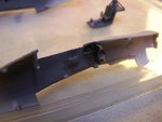
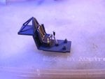
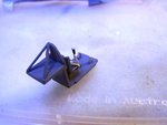
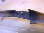
Progress. I decided to add some further cockpit detail, but details were very sketchy and I did not want to go to the expense of buying an aftermarket kit. i basically scrounged a few bits and pieces of leftover Pe from other models...throttle control levers from my sea fury , starboard side electical circuit box and gauges from my firefly build. I added the throotles control box fom my own build (3mm square section styrene, cut to length, then fiked down to 2mm on two sides. i then attached the Fury control unit to produce a facsimile of the moranes rather unique throttle assembly).
The big buff coloured box is meant to be the map case I saw in one of the photos.
i made the pilot harness from scrap lengths of Pe that ive kept. Not quite finished there....have not yet stuck the ends down to the pilot seat. i always struggle with that...usually too much glue and smeared mess everywhere. ill get the courage to try soon enough....
Attachments
Vic Balshaw
Major General
Now this is 'Scratch Building'. Well done Michael.
Airframes
Benevolens Magister
Good work Michael, and a visible improvement in your skills with each up-date.
If adding the throttle lever, remember that, being a French aircraft, the throttle worked in the opposite direction to most European and US aircraft (apart from Poland and maybe another one or two countries). So, when 'closed', the lever would be fully forward.
If adding the throttle lever, remember that, being a French aircraft, the throttle worked in the opposite direction to most European and US aircraft (apart from Poland and maybe another one or two countries). So, when 'closed', the lever would be fully forward.
- Thread starter
- #29
parsifal
Colonel
If you guys can tell if ive got the throttles arranged correctly or not, i will fly over and buy you a beer I think. I can see them with the magnifying glass, but I cannot see them with naked eye, or rather I can just see them but its impossible for me to work out the throtle arrangement. They are a couple of tiny tiny sticks pointing to the top of the cockpit. i will be amazed if they are visible with the clear cover on.
Im just happy i have throttles
Update. I dry fitted the two fuselage halves and had to move the throttles and the map case. other bits are okay. That goodness for debonder is all i can say. It came apart and back together pretty well, but i had to be careful not to apply too much debonder...just a small drop, so as not to loosen the throttle levers from the box ive made
before I stitch it all up, do you guys have any cockpit schematics or photos?
- Thread starter
- #31
parsifal
Colonel
wotjek, you are amazing. thankyou
fubar57
General
Ask and ye shall receive. Outstanding Wojtek.
Geo
Geo
Catch22
Major
Nice work!
Excellent find Wojtek!
Vic Balshaw
Major General
You're the man Wojtek, great set of pit pics.
- Thread starter
- #37
parsifal
Colonel
Hi guys.
After viewing the layouts posted by Wotjek, I was reasonably happy with the cockpit details that i dis do. I added a few bits and pieces, but specae was really limited, and so there was a limit to what i could do. I may add the gunsight, but that will come a bit later. all in all, pretty happy with the way my homemade cockpit details worked out.
Ive glued the two halves, attached the wings and the tail control surfaces. Everything has gone together quite nicely. this is a good quality product from Hasegawa, and im going very carefull in the step by step progress.
but i have some further questions. sorry guys, but this is an aircraft i dont know a lot about I am finding. i thought I did, but when it gets down to it, a lot of the details I didnt know. Im considering making the cockpit canopy open, as i think this will look a lot more dramatic than keeping the cockpit buttoned up. Ive also noticed that the tail has these support spars either side of the tail. The kit doesnt seem to have these, though I will check again tonite. I will need to fabricate them myself if they are not in the kit. Pretty easy I would think
Something definately not included in the kit are the exhaust stacks and flame covers. The exhaust stack may be shown as a sort of moulding detail on the fuselage halves (again I will check), but the flame covers are definately not there. Im considering attempting to make these from leftover PE scrap as well, but I need some details on their shape before i can attempt this. Would they be similar to the British types. I fitted flame covers to my Firefly, and these had rounded ends. if i were to attempt making similar flame covers myself, i would need to cut the PE strips to length and then work out a way to round the ends. Not at all easy, given how easy it is to bend or warp the PE. im think of cutting the PE to length, and then sandwiching it between either styrene or thin wood ply, then using a needle file to get the desired shape whilst holding the whole assembly in the vice or clamps. So that both flame covers are the same shape and length, I would put both of them into the same jig.
But, before all of this, I need better details of the shape of these covers. Does anyone have any information in that regard? I kinda feel very cheeky asking this, sqawking like a hungry bird, after all that was done by wurger to help me, but then again, i can only ask I guess.
By the exhaust stacks and flame covers you meant the Bronzavia exhaust pipes I guess. The system of exhausting was used for initail series only. The late series had the standard exhaust pipes seen in many pictures. Also the Bronzavia pipes were removed later too. I hope these shots ( the source - the net...) will help you with these Bronzavia exhaust pipes.


Last edited:
And if I grasped correctly there is a problem with these tail struts for the horizontal stabilizers ( tail support spars ). However these should come with the kit ... parts A4 and A5.
In case these haven't been attached, here a couple of images that can come in handy for making them from scratch.


In case these haven't been attached, here a couple of images that can come in handy for making them from scratch.
Lucky13
Forum Mascot
Users who are viewing this thread
Total: 1 (members: 0, guests: 1)


