Navigation
Install the app
How to install the app on iOS
Follow along with the video below to see how to install our site as a web app on your home screen.
Note: This feature may not be available in some browsers.
More options
You are using an out of date browser. It may not display this or other websites correctly.
You should upgrade or use an alternative browser.
You should upgrade or use an alternative browser.
**** DONE: GB-45 1/48 Gloster Gladiator - BoB/Foreign Service
- Thread starter Crimea_River
- Start date
Ad: This forum contains affiliate links to products on Amazon and eBay. More information in Terms and rules
More options
Who Replied?fubar57
General
Good stuff Andy
- Thread starter
- #103
Crimea_River
Marshal
Thanks George. The model is sapping my mojo right now. I tried to represent the exhaust ring with Tamiya light sensitive putty. Small variations were filled with Tamiya grey primer which apparently doesn't stick to that putty. Gonna let it sit for a bit. In the meantime I stuck on the lower wings but there is a slight difference in dihedral. The wing joints are very tight and there's very little wiggle room to adjust for that so I'm having to use a bit of brute force.
dneid
Staff Sergeant
Hey, Andy,
One thing about being back is YOU! I just love your work and I learn from everyone of your builds. You inspired me to add a lil fiddly stuff to the 109 I am working on while waiting for the P-40B PE set. I did a little scratch build on the throttle for the cockpit. I flattened a bit of sprue and filed / sanded it down and added a bit if round rod. I then added a lil more bulk with some Gorilla Glue. Pic below shows it in place, but painted or final finish yet.
One thing about being back is YOU! I just love your work and I learn from everyone of your builds. You inspired me to add a lil fiddly stuff to the 109 I am working on while waiting for the P-40B PE set. I did a little scratch build on the throttle for the cockpit. I flattened a bit of sprue and filed / sanded it down and added a bit if round rod. I then added a lil more bulk with some Gorilla Glue. Pic below shows it in place, but painted or final finish yet.
Attachments
- Thread starter
- #106
Crimea_River
Marshal
Kind words Dale, thank-you. Nice job on the throttle!
Going to take my exhaust ring now.
Going to take my exhaust ring now.
Lovely work so far Andy!
- Thread starter
- #108
Crimea_River
Marshal
So here's what I've been up to.
After all of the individual stub exhausts were in place, I created a representation of the exhaust ring by applying some Tamiya Light Curing Putty. This stuff was applied over some thick CA which I tried to use at first and which was a total failure due to shrinkage cracks and ripples appearing. The putty is more dimensionally stable, a little thicker than toothpaste, and can be worked for some time before placing it under a fluorescent light to cure. Despite this, I was still unable to achieve a consistent shape so I decided to brush some Tamiya Surface Primer over it, concentrating more on areas that needed to be filled. After the paint had dried, I tried to file down some high points and discovered that the primer didn't adhere to the putty so I left it all alone. for a while. Here's what it looked like this morning:

Doing anything more to shape the ring was probably gong to make things worse so I went ahead and mixed up some paints to do the final coat on the ring. Fortunatley, the Tamiya silver was getting quit thick so I again was able to use the mix as a bit of a leveller. Anyway, after painting, here's what things looked like:

I suppose it looks not too bad but certainly not resin-part quality. Anyway, the next step was to finish off the engine area by adding the various struts that hold up the cowls. Stretched sprue with the ends dipped in CA did the trick:

After a dash of silver on the struts, this will all be behind me.
Thanks for watching.
After all of the individual stub exhausts were in place, I created a representation of the exhaust ring by applying some Tamiya Light Curing Putty. This stuff was applied over some thick CA which I tried to use at first and which was a total failure due to shrinkage cracks and ripples appearing. The putty is more dimensionally stable, a little thicker than toothpaste, and can be worked for some time before placing it under a fluorescent light to cure. Despite this, I was still unable to achieve a consistent shape so I decided to brush some Tamiya Surface Primer over it, concentrating more on areas that needed to be filled. After the paint had dried, I tried to file down some high points and discovered that the primer didn't adhere to the putty so I left it all alone. for a while. Here's what it looked like this morning:
Doing anything more to shape the ring was probably gong to make things worse so I went ahead and mixed up some paints to do the final coat on the ring. Fortunatley, the Tamiya silver was getting quit thick so I again was able to use the mix as a bit of a leveller. Anyway, after painting, here's what things looked like:
I suppose it looks not too bad but certainly not resin-part quality. Anyway, the next step was to finish off the engine area by adding the various struts that hold up the cowls. Stretched sprue with the ends dipped in CA did the trick:
After a dash of silver on the struts, this will all be behind me.
Thanks for watching.
fubar57
General
Turned out nice very Andy. You well know we are are hardest critics
Airframes
Benevolens Magister
Looks the biz.
- Thread starter
- #112
Crimea_River
Marshal
Thanks very much chaps. I'm thinking ahead to the camouflage colours and have prepared a colour diagram that will be the "legend" going forward. I have a discussion going on with a Norwegian chap named Nils on another forum who has info from a 1939 document. He's the same chap who provided the additional pictures of 433 posted earlier. Though I've identified 7 potentially different colour combinations, it's possible, if not likely, that some of these will be duplicated (2 and 3 for example). The reason that there is some doubt is because the 1939 document suggests that the colours were the same as used on Caproni Ca.310s: Silver blue, beige and green.

Broad, brushing the various descriptions, a starting point for the discussion will be:
1 = light blue waves over base silver
2 = 3 = 6 = 7 = green
4 = 5 = beige
I'll keep y'all posted about what comes out and would welcome any knowledgeable input from you good folks if you feel inclined.
Broad, brushing the various descriptions, a starting point for the discussion will be:
1 = light blue waves over base silver
2 = 3 = 6 = 7 = green
4 = 5 = beige
I'll keep y'all posted about what comes out and would welcome any knowledgeable input from you good folks if you feel inclined.
- Thread starter
- #113
Crimea_River
Marshal
So I've not been ignoring this build. It's just been at that stage where I'm constantly filling and sanding seams in preparation for paint which, this being a biplane, needs to be attended to sooner than later since access will be obstructed by the upper wing.
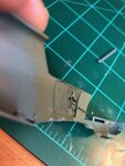
Below shows the pain in the butt seam access in the lower wing root. There is surface detail very close to the seam that I did not want to damage so access with files and sanding pads was extremely limited. I had to use thin strips of wet 800 grit paper that kept tearing. Grrrr. Note that what appears to be a severe pain run on the nose is actually just water. Runny nose, he he!

The underside seam was addressed with putty and primer a couple of times before rescribing and adding small details. I fashioned two spent ammo chutes out of brass shim stock and the drains are tube and solder. A small slip of the scriber that I didn't notice before now shows up in this photo. I'll go over that with a fine brush of primer.

I probably should have done the above after sticking the landing gear on but I dry fit and adjusted the latter so often that the fit is pretty good and will require minimal fill. Here the struts have been glued in place.

As always, I want to be sure everything is straight and symmetrical so a check of the wing clearance on both sides was done. It was a little off so the undercarriage was "persuaded" a bit before the glue set. All good now.

I'll keep plugging away as there's bugger all else to do! TTFN.
Below shows the pain in the butt seam access in the lower wing root. There is surface detail very close to the seam that I did not want to damage so access with files and sanding pads was extremely limited. I had to use thin strips of wet 800 grit paper that kept tearing. Grrrr. Note that what appears to be a severe pain run on the nose is actually just water. Runny nose, he he!
The underside seam was addressed with putty and primer a couple of times before rescribing and adding small details. I fashioned two spent ammo chutes out of brass shim stock and the drains are tube and solder. A small slip of the scriber that I didn't notice before now shows up in this photo. I'll go over that with a fine brush of primer.
I probably should have done the above after sticking the landing gear on but I dry fit and adjusted the latter so often that the fit is pretty good and will require minimal fill. Here the struts have been glued in place.
As always, I want to be sure everything is straight and symmetrical so a check of the wing clearance on both sides was done. It was a little off so the undercarriage was "persuaded" a bit before the glue set. All good now.
I'll keep plugging away as there's bugger all else to do! TTFN.
Airframes
Benevolens Magister
Good stuff Andy.
I think that, when I eventually get around to doing my Gladiators, i'll start on the 'Inpact' kit first !
I think that, when I eventually get around to doing my Gladiators, i'll start on the 'Inpact' kit first !
- Thread starter
- #116
Crimea_River
Marshal
Thanks Terry. Again I don't want to leave the impression that this kit is shite as that's far from the case.
Airframes
Benevolens Magister
Oh, I understand that Andy. It's just that this will be my first biplane for some time, and I think the old 'Inpact' kit might be a bit easier in parts, especially for my knackered hands !
Great work so far Andy!
- Thread starter
- #119
Crimea_River
Marshal
Thanks Hugh. Addition of details continues.
Studying detailed pictures, I drilled holes for the oil filler cap and one lower down for some kind of vent or drain.

The filler cap was then punched from card and some details added. The vent tube is solder and I hollowed the cut end with a pin.

On each side of the fuselage, there appears to be some kind of air outlet consisting of a hole and a half-round cover. The port side has a raised detail for this but it's not very convincing. The starboard side has nothing. Note also the joint of the undercarriage to the fuselage which needs work (a result of my aforementioned persuading).

Here you see the vent hole drilled and the cover plate attached. Yet another vent pipe was added over the gun trough. The repair to the undercarriage joint is underway using stretched sprue glued in with TET.

On the tail end, the rudder actuator cables were added using stretched sprue.

And here we go with the rigging. For this, I had previously bought some metal resistance wire from a vaping company (see post 4) but I've since learned of a tip using a different material that works extremely well. The secret is this stuff:

You can buy it on line but if you live near a store that specializes in knitting products, you may be able to pick some up there. I got my roll for 7 bucks and it should last me a lifetime. This stuff is an elastic material that is knit into clothes that need to be stretchy, like socks and hats. In addition to being stretchy, the cross section is also rectangular which is perfect for rigging since most aircraft rigging is not round but aerodynamically flat. Drill a tiny hole (my smallest drill at the moment is 0.5mm which is a bit large - I broke my 0.3mm which is ideal) dip one end of the elastic into a blob of CA, put some accelerator into the hole and stick in the rigging. At the other end, cut the elastic short of the end point, dip into CA, add accelerator into the hole, put the elastic in and let go. Bob's your uncle - a nice, tight length of rigging.
Here's the end result of my first try at the tail end. All of this rigging was achieved with just two lengths of this material.

The holes have since been filled with a bit more CA to cover them up. I'm pretty happy with this material and now my vaping wire is up for grabs if anyone want it!
Studying detailed pictures, I drilled holes for the oil filler cap and one lower down for some kind of vent or drain.
The filler cap was then punched from card and some details added. The vent tube is solder and I hollowed the cut end with a pin.
On each side of the fuselage, there appears to be some kind of air outlet consisting of a hole and a half-round cover. The port side has a raised detail for this but it's not very convincing. The starboard side has nothing. Note also the joint of the undercarriage to the fuselage which needs work (a result of my aforementioned persuading).
Here you see the vent hole drilled and the cover plate attached. Yet another vent pipe was added over the gun trough. The repair to the undercarriage joint is underway using stretched sprue glued in with TET.
On the tail end, the rudder actuator cables were added using stretched sprue.
And here we go with the rigging. For this, I had previously bought some metal resistance wire from a vaping company (see post 4) but I've since learned of a tip using a different material that works extremely well. The secret is this stuff:
You can buy it on line but if you live near a store that specializes in knitting products, you may be able to pick some up there. I got my roll for 7 bucks and it should last me a lifetime. This stuff is an elastic material that is knit into clothes that need to be stretchy, like socks and hats. In addition to being stretchy, the cross section is also rectangular which is perfect for rigging since most aircraft rigging is not round but aerodynamically flat. Drill a tiny hole (my smallest drill at the moment is 0.5mm which is a bit large - I broke my 0.3mm which is ideal) dip one end of the elastic into a blob of CA, put some accelerator into the hole and stick in the rigging. At the other end, cut the elastic short of the end point, dip into CA, add accelerator into the hole, put the elastic in and let go. Bob's your uncle - a nice, tight length of rigging.
Here's the end result of my first try at the tail end. All of this rigging was achieved with just two lengths of this material.
The holes have since been filled with a bit more CA to cover them up. I'm pretty happy with this material and now my vaping wire is up for grabs if anyone want it!
Users who are viewing this thread
Total: 1 (members: 0, guests: 1)