P-47 'Bridge Buster', 1/48th scale, 9th Air Force Diorama. (2 Viewers)

Ad: This forum contains affiliate links to products on Amazon and eBay. More information in Terms and rules

Thanks very much Jim, glad you like it - makes it all worthwhile.

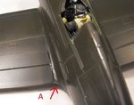
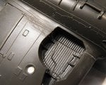
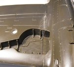
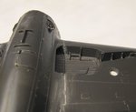
George, do you mean the 'scoop' shape outlet beneath the fuselage? If so, I've always seen it in either the camouflage colour, or bare metal on an overall 'silver' machine.
Can't say I've seen burnt metal, although I have seen what appears to be dirt/mud/ dirty water stains etc. The supercharger shutters on the fuselage side were certainly 'fuselage' colour, normally white, where the end of the 'star and bar' insignia was on US aircraft.
I'm OK for B-26 stuff now - but I was struggling a bit when I was building a 1/48th scale example some years back!

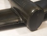
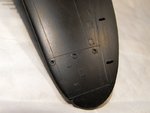
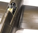
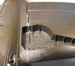
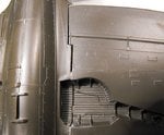
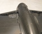
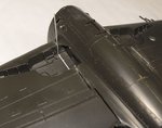
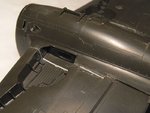
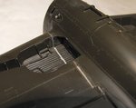
Just about to photograph the wings to date, and then start on the gap filling - should have some pics later.
 
Jumping Jupiter Terry, you ain't lost your touch mate, that little old pilot strapped in ready for action, looks terrific, even down to the skin tones.
 
Thanks very much Vic. I'm relatively pleased with it, although the face, arms and helmet took some wear due to handling, and the PVA in the goggles has shrunk back a bit. Of course, it looks better in 'real life' than in the harsh close-up shots, and it'll get some re-touching once the model is painted and the masking removed from the cockpit area.
 
OK, a little progress, with the wings on.
The following pics are mainly for the benefit of George, to show the wing root gaps, particularly in the wheel bays, and how to (hopefully) correct the problem.
I'm about to continue with the corrections, so I'll post pics of the stages later, but meanwhile, here's what things are like at the moment.
PICS 1 to 3. The cockpit air conditioning intake and gun camera ports drilled and cut, but yet to be sanded, recognition signal lamps countersunk, and will be gently sanded then painted and glazed after the model is painted, and finally, the landing lamp, drilled, reamed, and backed with scrap plastic. Again, this will be 'silvered' with foil, and glazed after painting the model.

The wing before corrections:

PICS 4 and 5. Starboard wing root, top.
PICS 6 to 8. Underside and wheel well, starboard wing.
PICS 9 to 12. As above for port wing. The arrowed 'A' shows the wing root fillet, trimmed and sanded to align with the wing itself, removing the 'step' originally present.
As can be seen, it's nothing serious, and I'm relatively confident that the corrugations inside the wheel wells can be continued, after a fashion, once stretched sprue is laid in the joint and then 'notched' to represent the ribs.
I'm going to see if the moulded guns survive - which is doubtful - but if not, then they'll be cut off, the wing drilled, and suitable metal tubes inserted instead - given the cutting discs for my rarely used motor tool arrive in time. I thought I'd found a suitable tube cutter, but the minimum diameter it can cut is 3mm, and the tubes for the guns are a midgies over 1mm.
I'm keeping my fingers more crossed than usual that the pitot tube survives, as that 'fin' on the end will be a b*gg*r to replicate if I have to scratch-build one!
I should have further pics later today.
 

Attachments

  • P-47 Build 070.jpg
    P-47 Build 070.jpg
    62.4 KB · Views: 261
  • P-47 Build 073.jpg
    P-47 Build 073.jpg
    81 KB · Views: 258
  • P-47 Build 074.jpg
    P-47 Build 074.jpg
    113.9 KB · Views: 251
  • P-47 Build 069.jpg
    P-47 Build 069.jpg
    98.4 KB · Views: 245
  • P-47 Build 071.jpg
    P-47 Build 071.jpg
    116.4 KB · Views: 269
  • P-47 Build 077.jpg
    P-47 Build 077.jpg
    109.5 KB · Views: 210
  • P-47 Build 078.jpg
    P-47 Build 078.jpg
    114 KB · Views: 243
  • P-47 Build 079.jpg
    P-47 Build 079.jpg
    75.5 KB · Views: 249
  • P-47 Build 072.jpg
    P-47 Build 072.jpg
    108.1 KB · Views: 245
  • P-47 Build 075.jpg
    P-47 Build 075.jpg
    129.5 KB · Views: 262
  • P-47 Build 076.jpg
    P-47 Build 076.jpg
    78.8 KB · Views: 258
  • P-47 Build 081.jpg
    P-47 Build 081.jpg
    52.3 KB · Views: 253
You're doing a great job on that old kit Terry. I must say I cringe a bit when considering the logic of putting a seam right down the middle of those wheel well corrugations. Using present day knowledge to question 40-year-old logic though, I must admit, well, illogical. The excellent Tamiya kit extends the corrugated section right over to the fuselage wall, though there is a fair gap at that point as well.

Keep up the great work.

I think George is talking about the metal plate behind the turbo waste gate. This is an area for which it's hard to find pictures, given how inaccessible it is on the ground. Tamiya suggested a burnt metal colour, which I followed:

13120522.jpg
 
First, thanks Wojtek and Andy.
Second - Ah! That bit!
Now that it's been mentioned, I'll need to check, although I doubt those photos showing the underside will be conclusive. I would have thought there would be at least some heat discolouration, so I'd guess any form of 'burnt metal' or similar colour would suffice.
I'm very surprised that, on my kit, this area has joined without a prominent seam, gap, lump or ridge, as every P-47 kit I've built, in all scales, has had a gap of some sort, which is a b*gg*r to correct easily!

Now on to those corrugations. I vaguely recall, many years ago when building this kit, that the joint was so good, the 'ribs' appeared to continue, and the wings virtually locked into position, hardly needing glue. But, with all the use the moulds have had, it's not surprising there's a visible gap these days. Bearing in mind that when this kit was first produced, and economics versus available (and affordable) moulding technology of the day, plus 'real' modellers expectations back then, the method of moulding and joining would have been acceptable. More so as kits were mainly aimed at 'average, mass market' audiences, with more than a passing nod to keen modellers, in the form of what was then exceptional detail. Nowadays, techniques such as spark erosion are used in mould tool production, but that is still very expensive even today, as reflected in the prices (or at least part of the price) of some modern kits, and, had it been widely available back then, the cost would have been extremely prohibitive for the production of items which, in manufacturing and marketing terms, are mainly classed as part of the toys industry.

Anyway, on to the corrections, and again, the photos are mainly for the benefit of George, for his GB entry.
PIC 1. Stretched sprue, slightly thicker than required to fill the gap, was laid into the gap running across the wheel bay corrugations. Thinner sprue was glued into the vertical gaps, virtually flush with the surrounding surfaces, and is here shown before trimming, which was done once set.
PIC 2. When fully set, the vertical pieces were trimmed, and then gently sanded and scraped with the edge of a scalpel blade.
PIC 3. This is the starboard wheel well, which had a much bigger gap to fill and, although it's difficult to see in the photo, the stretched sprue has been shaved down, level with the top of the corrugated 'ribs', and then notches cut, using first the scalpel, and then a small modelling chisel. This was followed by light filing, using a 'knife blade' jewellers file, in a light 'sawing' action, between the ribs. The gaps between the wing underside and the root were also filled with stretched sprue and sanded smooth, leaving the area at the end of the flaps open.
PIC 4. The port wheel well only required a very thin 'thread' of stretched sprue, and a similar technique was used to create the ribbed effect. The excess glue seen here, barely visible to the naked eye, has since been filed away, during the 'notching' process, again using the 'knife blade' file.
PIC 5. This is the small, extremely sharp, modelling chisel used, shown alongside a standard Swann Morton No.3 scalpel handle with 10A blade, for comparison. This is a very useful tool, and allows for some precision shaving and cutting - well worth adding to the tool box.
PIC 6. Again somewhat difficult to see here, but the short gaps in the upper wing roots have been filled with a bead of PVA, once again leaving the gap at the end of the flap open. As the PVA dries clear, it's not always possible to see if the gap is completely filled, but, once the model is primed, any additional filling required can easily be accomplished with a further bead of PVA, applied off the end of a sharpened cocktail stick.

Next step, which I'd much rather do after painting, is to complete the gun sight, paint and fit the armoured glass, and then mask, paint and fit the windscreen. Had the pilot figure not been in place, the cockpit could have been masked without fitting the windscreen etc, but this is needed to support the masking tape, keeping it away from the pilot and gun sight as much as possible. I might also fit the canopy, temporarily, in the closed position, although there's a risk that a fine mist of over-spray could get between the gaps, so I'll have to think about it - maybe after a glass or three of wine .....
Thanks again for the compliments and general interest, and it's good to be back at the bench, even though it's hard going at the moment. Hopefully, I'll be able to get the model primed, and show some more progress pics soon.
 

Attachments

  • P-47 Build 087.jpg
    P-47 Build 087.jpg
    71 KB · Views: 237
  • P-47 Build 089.jpg
    P-47 Build 089.jpg
    81.4 KB · Views: 232
  • P-47 Build 092.jpg
    P-47 Build 092.jpg
    88.5 KB · Views: 211
  • P-47 Build 093.jpg
    P-47 Build 093.jpg
    108.9 KB · Views: 240
  • P-47 Build 097.jpg
    P-47 Build 097.jpg
    71.4 KB · Views: 231
  • P-47 Build 095.jpg
    P-47 Build 095.jpg
    94.2 KB · Views: 209
That helps a lot Terry. With regards to the superchargerexhaust, you're quite right saying it's camo or natural metal, but I've posted some photos on my build(Don't want to clog your thread up) to show you what I mean.

Geo
 
Thanks mate. it's good to be back, but it's bl**dy awkward work, and still uncomfortable and frustrating. Even very simple tasks take a long time, a lot of effort, and numerous attempts - it's driving me more nuts than I am already!
But, if I'm going to mess-up, I'd rather do it on one of my own models, than ruin a commission or museum model. Not ready to tackle those outstanding jobs yet, but once the injections take effect properly, I might be able to give it a go.
 
These might help Terry, not sure.
 

Attachments

  • IMG_6051 resized 25.jpg
    IMG_6051 resized 25.jpg
    74 KB · Views: 225
  • IMG_6059 resized 25.jpg
    IMG_6059 resized 25.jpg
    116.3 KB · Views: 239
  • IMG_6058 resized 25.jpg
    IMG_6058 resized 25.jpg
    97.3 KB · Views: 235
  • IMG_6060 resized 25.jpg
    IMG_6060 resized 25.jpg
    104.5 KB · Views: 227
  • IMG_6061 resized 25.jpg
    IMG_6061 resized 25.jpg
    99.6 KB · Views: 243
  • IMG_6062 resized 25.jpg
    IMG_6062 resized 25.jpg
    98.7 KB · Views: 219
  • IMG_6072 resized 25.jpg
    IMG_6072 resized 25.jpg
    66.8 KB · Views: 193
  • IMG_6075 resized 25.jpg
    IMG_6075 resized 25.jpg
    109.9 KB · Views: 237
Thanks Aaron, some useful pics there, from different angles to some I have. I probably won't bother doing a lot of wheel well detail (yeah - right!), but I will be improving the fairly basic gear legs.
I'm just about to start carving and sanding the plastic blocks I had to glue around the front of the nose, to support the engine cowling. I might not add any detail to the engine itself, as it's mostly hidden in the cowl, and by the prop, so I might have some pic later tonight.
But then again, the odd wire or so might fin its way in there .............!
One of these days, I will do a model out of the bl**dy box!!!
BTW, that's the first time I've actually seen the turbo, inside the exit duct - great pic!
 
Last edited:
Quoted by AF
One of these days, I will do a model out of the bl**dy box!!!

NOT!!!!!:lol:

BTW, that's the first time I've actually seen the turbo, inside the exit duct - great pic!

I had to lay on my back to get that shot.:lol:
 
Doing a fine job there Terry, especially fixing the wheel well corrugations.

...... I might also fit the canopy, temporarily, in the closed position, although there's a risk that a fine mist of over-spray could get between the gaps, so I'll have to think about it - maybe after a glass or three of wine ......
What I've done it that situation in the past is glue the sliding canopy on with Testors clear parts glue making sure it also seals the gap between canopy and windscreen, then after painting, pull it off and peal the cement off with a chisel end toothpick. Only some minor touch up painting will be needed as long as you're careful with the glueing. Don't let this deprive you of those glasses of wine though.......
 
Thanks Hugh.
Glenn, I'd considered doing just that. However, I'm going to have a go at just masking over the pilot, cockpit and gun sight first, as I'd rather fit all the delicate bits, and the windscreen, after painting. this will also allow me to mask the screen and canopy and match the paint colour to the rest of the model.
Just got delayed after going to the local shop, as it was p*ss*ng down, and I've had to dry off, and change trousers etc !
So, an hour-ish late, i'm about to start on the engine and cowling - pics later, all being well.
 

Users who are viewing this thread

Back