Super Detailing S.E.5 Guillow's model

Ad: This forum contains affiliate links to products on Amazon and eBay. More information in Terms and rules

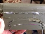
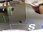
Okay guys, we now begin our little soree' into the wonderful world of stitching without using the needle. Keep in mind that I had to use the old scratched out practice fuselage section to take new pictures for this post to show you my techniques. Remember too, that the underside of the fuselage was purposely left open until all detailing, stitching, and accessories were completed and installed.

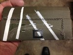
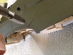
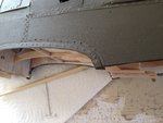
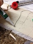
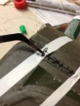
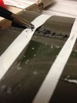
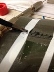
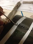
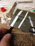
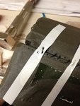
We start out with the practice scrapped fuselage section to show you (again) my trials and experiments to see if my ideas would work. From these different concepts, I then applied my techniques to the model itself. My first stage was to use a hand held pin vise to drill all the holes necessary for the threads to go through. Here, on the fuselage to the model, you can see what I'm doing. You can easily see that the pin vise is really slow and tedious, but it's safe to use against a fragile balsa fuselage and I have more control over how much pressure to put onto the drill bit. ** Special note, drill the hole at least 50% bigger than the thread. Because the hole will shrink a bit from the covering over the balsa, plus the thread will tend to fray out when using it.
 

Attachments

  • Proof 1.jpg
    Proof 1.jpg
    50.7 KB · Views: 66
  • SE5 166.jpg
    SE5 166.jpg
    269.4 KB · Views: 60
  • SE5 169.jpg
    SE5 169.jpg
    285.7 KB · Views: 65
  • SE5 170.jpg
    SE5 170.jpg
    255.2 KB · Views: 72
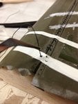
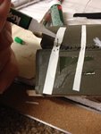
After all the holes were drilled out. I started with the thread. Here, I just used a very small drop of CA glue onto the very tip of the thread itself. Use only a very small amount of this glue and only on the very tip. Allow this glue to dry (about one minute). What happens is the tip of the thread is now hard and will act as its own needle point to help me push the thread through the hole. If I did not make the tip harden, the thread would only spread (fray) out when trying to thread it through the hole. This way, the tip of the thread stays harden and pointed.

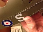
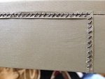
Next, I take this harden end of the thread, I add an additional amount of CA glue to the tip and push it through the first (of many) holes. The additional glue will help hold the harden tip inside the hole, leaving the rest of the thread out and very flexible. After awhile, with lots of practice, I began to cut smaller and smaller pieces of thread (as can be seen in the third photo). But here, let's use this example to illustrate my technique. Everyone following so far?.
 

Attachments

  • S.E.5 stitching # 8.JPG
    S.E.5 stitching # 8.JPG
    265 KB · Views: 75
  • S.E.5 stitching # 7.JPG
    S.E.5 stitching # 7.JPG
    234.3 KB · Views: 73
  • SE5 178.jpg
    SE5 178.jpg
    280.2 KB · Views: 59
Next, the threaded end that was glued to the first hole is cut to a short length. Now, just like the opposite end, I'm applying just a tiny drop of CA glue to the very tip. Not the whole thread. This tip, just like the first one, will harden and start to act as its own needle point to help me push in the thread into the opposite hole.
 

Attachments

  • S.E.5 stitching # 11.JPG
    S.E.5 stitching # 11.JPG
    256.8 KB · Views: 53
Here's where the "magic" comes in. After the tip has harden (about one minute) I used a pair of small tweezers and simply bent the thread over itself and insert the harden end through the next hole. Please keep in mind, that the glue on the tip has already completely dried and only hardened the tip. This will help to push the rest of the thread through the hole without any resistance. Just keep working on using the tweezers to twist the thread over itself and further into the hole. At the last minute, I used a long "T" pin to push in the final amount of thread into the hole.
 

Attachments

  • S.E.5 stitching # 12.JPG
    S.E.5 stitching # 12.JPG
    212 KB · Views: 57
  • S.E.5 stitching # 5.JPG
    S.E.5 stitching # 5.JPG
    183.2 KB · Views: 63
  • S.E.5 stitching # 4.JPG
    S.E.5 stitching # 4.JPG
    186.9 KB · Views: 62
  • S.E.5 stitching # 3.JPG
    S.E.5 stitching # 3.JPG
    191.9 KB · Views: 68
With the end of the thread sticking out from the inside, I used a small set of needle-nosed pliers to pull the remaining thread tight. Once it's tight. I used another very small drop of CA glue to "seal" in the thread to its place. And there you have it. I tried to get all of the threads as close to the patterns as possible. However, I found that slightly variations from individual threads help to add "life" to the stitching and gives it a sense that it was worked on by human hands, just like the full-sized aircraft.

On my model, I opted for silver-colored thread for two reasons: 1) to help give it a more appearance of stranded wire that was silver in color and 2) the silver helped to "pop" out the contrast between the olive drab colored fabric and the bright threads.

It's a long and (somewhat) tedious process, but I enjoyed it and with each stitch, the fuselage became more "alive' and special that only comes with the S.E.5. Voila'!!
 

Attachments

  • S.E.5 stitching # 2.JPG
    S.E.5 stitching # 2.JPG
    309.3 KB · Views: 57
  • S.E.5 stitching # 1.JPG
    S.E.5 stitching # 1.JPG
    287.8 KB · Views: 55
  • S.E. 5 reduced # 218.jpg
    S.E. 5 reduced # 218.jpg
    35.6 KB · Views: 66
  • SE5 178.jpg
    SE5 178.jpg
    280.2 KB · Views: 54
My dear Skye, I am convinced that this hobby puts obstacles, tests and challenges that influence, modify and / or reaffirm our mentality towards the outside world and loved ones.
Patience, inventiveness, creativity, tolerance to failure and perseverance, since I took this hobby more seriously, has become my "therapist at home" (it has not been cheap in its rates). :pompous:

Your technique and explanation have been very clear and I will be aware of your progress.

Muy bien logrado hasta ahora :thumbup:
 
Mr. Sancer: Mucho gracias senior! It's very rewarding to heard from a fellow modeler using such comparative analogy in Life with modeling. I too, share exactly what you mean. I believe I speak for many of us here on this site and around the world, that modeling is very therapeutic. I was born almost totally deaf. In anticipation of your question, yep, I speak and understand sign language (ASL and the "street version"). When growing up, as a young boy, I was ostracized from many other children because they didn't understand my "uniqueness." I found modeling to be my sanctuary and relief. Oddly enough, when I was 33, I managed to acquire a special waiver from the FAA that allows me to obtain a private pilot's license. Raised a family and now a grandfather 6 times over. Got lots to share, but that's outside of the scope of this site.

Mr. Wurger, you and I share much in common as well. It's always a pleasure to see and hear from you on this site.

The S.E.5 has indeed posed its own unique challenges and really gave me a chance to focus on how best to achieve the desired results that emulated the full sized aircraft, yet not come off too "toy-like." There were many details I had to leave off due to the small size of the model for just that reason. Still, it was extremely satisfying to see the results. With your blessings, I'll shall continue posting more on the S.E.5 with the exhaust manifold detailing, the rest of the fuselage panel details (hope I can hear from Mr. Wurger's comments on this), and of course, the Lewis machine gun sitting so proudly on top of the whole model.

Thank you very much for your observations and comments. Always appreciated!

Sincerely,

Gary (Skye)
 
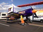
This is well outside the scope of this particular building thread on the S.E.5, but I just recently attended the famous Reno National Championship Air Races here in Reno, Nevada (my home). I thought you might appreciate the extreme modifications done to a WWII aircraft, In this case, a Grumman F8F Bearcat. This is the famous "Rare Bear" that has set numerous racing and climb to altitude records. In the last picture, that is me standing to the right. They also changed the airfoil to allow the plane to go faster, at a small sacrifice of not being able to take off from an aircraft carrier without using a long runway. I was very close friends with Lyle Shelton (previous owner) and John Penny (pilot) of Rare Bear. I was granted access to the cockpit interior. If anyone is interested, I'll post the interior. Very unique cockpit in which they had a special "pad" mounted to tell the pilot of any potential leakage of dangerous exhaust gases (carbon monoxide). It was also funny because right next to the throttle controls on the left side, they posted a small sign that says: "Go Fast, Turn Left."
 

Attachments

  • RB-# 7 ,1.jpg
    RB-# 7 ,1.jpg
    146.3 KB · Views: 43
  • RB-# 7, 3.jpg
    RB-# 7, 3.jpg
    160.9 KB · Views: 42
  • RB-# 7, 4.jpg
    RB-# 7, 4.jpg
    144.8 KB · Views: 44
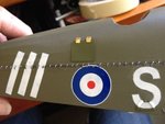
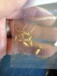
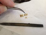
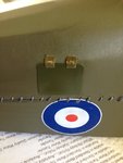
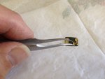
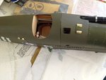
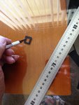
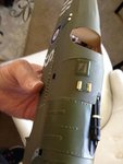
With the stitching finally completed, we can now move on to the access hatches and more panel details. I'm posting this slightly ahead of the steps I took to show my goal of installing the hatch just behind the pilot's cockpit on the right side. I purchased very small hinges from MicroMark. These hinges are mostly used for small doll houses on their doors. In this case, the scale of the hinges were perfect for my needs. I'm sure these hinges or something similar can be purchased at any local arts and crafts store. In the next photo, I filed down the excess hinge plates to make them more suitable for the S.E.5. That is a flat file laying just below the hinges and it also shows one of them filed down to size.

The panel itself was cut from glossy paper and pre-bent to conform to the curvature of the fuselage. The whole assembly was then first spray painted with matching olive drab paint (Tamiya) and then glued into place. I purposely left the hinges unpainted to see if they would look good. I decided that it was too much "bling" and distracting. So, I decided to paint them over with the same olive drab paint by brush. Still, as can be seen in the last picture, I brushed on only a thin coat of paint to allow some of the brass to show through to help give it that "metallic" authenticity look.
 

Attachments

  • SE5 185.JPG
    SE5 185.JPG
    230.5 KB · Views: 59
  • SE5 183.JPG
    SE5 183.JPG
    266.1 KB · Views: 62
  • SE5 184.JPG
    SE5 184.JPG
    212 KB · Views: 64
  • SE5 196.JPG
    SE5 196.JPG
    213.1 KB · Views: 63
The next item on my agenda was a small hatch in front of the window on top of the fuselage decking. As with the hatch behind the pilot's seat, I used the same small hinges filed down to size and used a small pin that came with the hinges (see the plastic bag in my previous post for the small pins) inserted and bent at right angles just like the full sized aircraft. Later, I will paint them olive drab as they too, as much I"d like to have some more "bling" and eye-candy, they were too distracting.
 

Attachments

  • SE5 186.JPG
    SE5 186.JPG
    185 KB · Views: 54
  • SE5 187.JPG
    SE5 187.JPG
    214.1 KB · Views: 60
One might think the pilot's window with its compound curves at the corners would pose a special challenge. It was actually very easy, once my imagination went into "overdrive." In this case, black flexible electrical tape came in handy. I simply cut out a small piece of clear plastic that was slightly oversized for the window cutout. Then I cut a special square with the cutout in the center from the electrical tape. Because the window was so small, I was able to cut the whole "frame" in one piece. What is not shown, is that I used the special MicroMark rivet decals on top of the tape. Then I painted the whole frame before gluing onto the fuselage.
 

Attachments

  • SE5 188.JPG
    SE5 188.JPG
    237.4 KB · Views: 56
  • SE5 189.JPG
    SE5 189.JPG
    211.7 KB · Views: 59
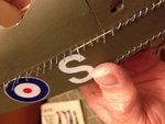
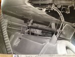
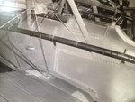
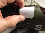
More detailing awaits on the other side of the fuselage. In this case, a cover over the ejector chute. The photos were personally taken at the RAF Museum about 35 years ago (this makes me 29 years old again for the 64th time). In the third photo, I'm using my tried-&-true practice of using paper to help fabricate a template to use for my panel. But first, I had to fabricate a small rounded support structure at the front of the Vickers gun. This was made from scrap pieces of soft 1/4' balsa cut to roughly between a "V" and "U" shape as close as possible to the ones depicted on photos from the Internet. Then the balsa pieces were each rounded off with sand paper and given a thin coat of filler to fill in the wood grain. From there, each separate piece was then given a coat of primer and sanded very smooth. Then they were glued together and painted whole.
 

Attachments

  • SE5 206.jpg
    SE5 206.jpg
    238.6 KB · Views: 59
  • SE5 207.jpg
    SE5 207.jpg
    257.9 KB · Views: 60
  • SE5 200.jpg
    SE5 200.jpg
    135.2 KB · Views: 52
  • SE5 201.JPG
    SE5 201.JPG
    204.6 KB · Views: 53
Last edited:
Airframes:

Thank you sir. Very much appreciated. Glad I was able to properly convey my builds for you to easily understand. It's not always easy to do this.
 

Users who are viewing this thread

Back