Super Detailing S.E.5 Guillow's model

Ad: This forum contains affiliate links to products on Amazon and eBay. More information in Terms and rules

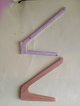
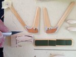
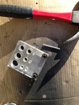
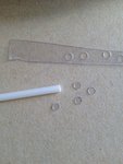
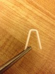
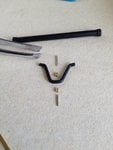
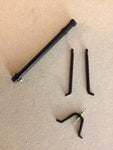
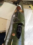
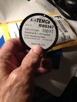
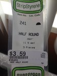
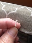
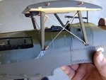
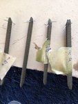
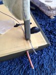
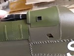
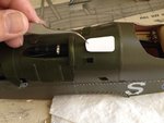
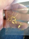
Crimea, Gnomey, and Wurger, I sincerely thank you all for enjoying my posts of the S.E.5. I'll be continuing. So, sit back and relax with your favorite beverage or chair. These pictures show that I've cut out another thin plastic piece from the paper template to be used as a cover over the ejector chute. A closer look reveals that I've also added some details around the opening to the ejector chute.

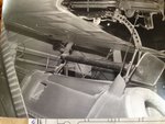
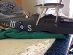
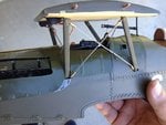
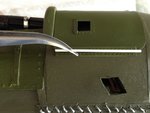
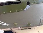
The next photo shows that by holding it over the fuselage, the green fabric shows through the hole. Well, we can't have that!

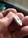
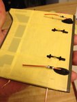
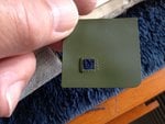
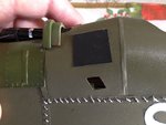
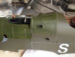
So, the next picture shows I've added a square piece of paper painted flat black and glued it into place approximately where the ejector chute would be located after the cover was glued in place.

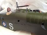
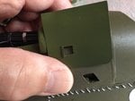
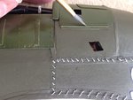
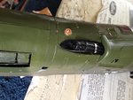
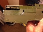
I was finally able to glue on the paneling into place. Now it looks like a real ejector chute. The black paper prevents the green from being seen.
 

Attachments

  • SE5 202.jpg
    SE5 202.jpg
    169.7 KB · Views: 52
  • SE5 203.jpg
    SE5 203.jpg
    153.4 KB · Views: 49
  • SE5 204.jpg
    SE5 204.jpg
    252.1 KB · Views: 55
  • SE5 205.JPG
    SE5 205.JPG
    238.3 KB · Views: 46
As the black and white photo shows, there appears to be another panel on top of the ejector chute paneling. So, we'll fabricate another panel as well. It was also at the point I decided to add the hinges to the paneling as well. I cut up some thin plastic strips and glued them into place. Next, I used a very thin plastic rod cut to the same length of the plastic strips and glued that rod between the two strips.

Then the whole hinge was hand-painted green to match.
 

Attachments

  • SE5 206.jpg
    SE5 206.jpg
    238.6 KB · Views: 48
  • SE5 209.jpg
    SE5 209.jpg
    187.6 KB · Views: 54
  • SE5 211.jpg
    SE5 211.jpg
    328.7 KB · Views: 50
  • SE5 208.JPG
    SE5 208.JPG
    169.7 KB · Views: 50
Now with the whole paneling in place over the Vickers machine gun, plus the extra ejector chute, and extra hinges, it all starts to look very well.
 

Attachments

  • SE5 213.JPG
    SE5 213.JPG
    228.1 KB · Views: 59
  • SE5 212.jpg
    SE5 212.jpg
    191.3 KB · Views: 56
As can be seen on the full sized fuselage of the S.E.5, there are some small hinges at the lower end of the front nose. Once again, I decided to use the same hinges for the paneling. These hinges are easily purchased through MicroMark catalog (for doll houses) or at your local arts and crafts store.

The small round circles near the engine cover are just the letter "O" from dry transfer sheet papers that were purchased at the local arts and crafts store.
 

Attachments

  • SE5 139.JPG
    SE5 139.JPG
    126.1 KB · Views: 47
  • SE5 183.JPG
    SE5 183.JPG
    266.1 KB · Views: 48
  • SE5 233.JPG
    SE5 233.JPG
    255.2 KB · Views: 48
  • SE5 234.JPG
    SE5 234.JPG
    266.2 KB · Views: 58
Landing gears: The stock landing gears from the Guillow's kit and my own updated version on the bottom of the first photo. Notice how the customized landing gear is more wider and robust than the thin balsa landing gear from the kit.
The second picture shows all of the customized components for the landing gears. I used basswood in place of balsa.
The last two photos show the bullet-shaped fairing to the landing gears. They were shaped out of soft balsa block, sanded, filled with Spackling Compound -a household filler- primed, and painted.
 

Attachments

  • SE5 221.JPG
    SE5 221.JPG
    140.7 KB · Views: 56
  • SE5 228.jpg
    SE5 228.jpg
    172.7 KB · Views: 53
  • SE5 230.JPG
    SE5 230.JPG
    162.8 KB · Views: 54
  • SE5 232.JPG
    SE5 232.JPG
    164.9 KB · Views: 54
Next, I decided to tackle the Aldis gun sight. This is a fragile item and I knew ahead of time that I would have to be prepared to protect it with the next step of adding the top wing center section and cabane struts as "protective umbrella." The lens for the gun sight was made from clear plastic sheets using a punch & die set. There were many reference sources for the gun sight. I just happen to use this one as well as several others. Since I personally took this picture, there should not be any copyright issues.

I used a thin diameter of plastic rod over boiling water to soften it enough to bend without breaking or kinking. This is the "A" frame to the gun sight. It was guessed at how high and wide it would be. I also had to temporarily install the top wing center section using the cabane struts and tape to guess how high it should go in relationship to the run rail for the Lewis gun that would be sitting on the top wing.
 

Attachments

  • SE5 222.JPG
    SE5 222.JPG
    405.4 KB · Views: 46
  • SE5 223.JPG
    SE5 223.JPG
    367.5 KB · Views: 48
  • SE5 206.jpg
    SE5 206.jpg
    238.6 KB · Views: 47
  • SE5 224.JPG
    SE5 224.JPG
    310.9 KB · Views: 46
  • SE5 226.JPG
    SE5 226.JPG
    246.6 KB · Views: 43
Wurger,

Thank you sir. I also sent you a personal email on my progress of the P=51. Did you receive it?
 
The sub assemblies are made up of small cut pieces of brass tubing and plastic. The lens are already installed on both ends of the gun sight. The gun sight is assembled separately and then installed on top of the fuselage. Because it is very fragile, I must immediately shelter it by installing the top wing center section and then surrounding it with rigging. There, the gun sight and top center section is all complete
 

Attachments

  • SE5 225.JPG
    SE5 225.JPG
    284 KB · Views: 46
  • SE5 229.JPG
    SE5 229.JPG
    331.7 KB · Views: 45
  • SE5 237.JPG
    SE5 237.JPG
    162.2 KB · Views: 45
  • SE5 238.JPG
    SE5 238.JPG
    196.4 KB · Views: 52
  • SE5 239.jpg
    SE5 239.jpg
    251.8 KB · Views: 54
Crimea,
Thank you very much. May I call to your attention that the S.E.5 model is only 1/12th scale? This translates to 27" wingspan. The Guillow's kit biplane was originally designed for rubber band powered flight. I just simply turned it into another level.

Airframes,

Thank you for your appraisal. It's very much appreciated. I'm honored.

Sincerely,
Skye
 
The first picture shows the top wing center section along with the rigging complete. To get to the stage, I have worked out the following methods. Please keep in mind, all of this was before I knew about a fantastic product called Vape metal strips.

They're used for Vape smokers, but I've found the metal strips for a much better (& healthier) use. Please allow me to post a picture of this product while we're on this topic of flat RAFer rigging. This is a type of rigging that is often overlooked by the majority of people not familiar with biplanes.

The Royal Aircraft Factory came up with an alternative to the stranded wires then in use on their early biplanes. They needed something stronger and more wind-resistance that would be more stable as the airspeeds increased due to more developed airframes and powerplants. The airfoil is somewhat shaped like an airfoil in cross section and comes in different sizes for different uses as well as different aircraft.

Up to this point, I could only use Evergreen 1/2 round strips of plastic .060" wide as a substitute to simulate the flat rigging. It is this plastic rigging that is on the model you see here and future posts. Evergreen also makes .040" wide strips as well, but at that time, I was not aware of this fact.

Until the discovery of the Vape metal strips, the only available flat rigging for scale models were for the larger 1/5th and 1/4th scales. They're usually purchased from Mick Reeves of U.K., Proctor Enterprise of Oregon, USA, DuBro of USA and Sullivan also of USA. They are much too large for the smaller scale models and I truly believe that the Vape metal strips in .4mm sizes are great for the plastic scale models of 1/32nd and in some cases down to 1/48th scale. For the S.E. 5, I wish I had known about this marvelous product, and I would've used the .8mm size.

The second, third and fourth photos show the two sizes of Vape metal strips. They can easily be purchased at local Vape shops and through Amazon. I was able to obtain 100-foot roll of two sizes: .4mm and ,8mm sizes. That's enough for me to model biplanes into the next century! Great for modeling...
 

Attachments

  • SE5 239.jpg
    SE5 239.jpg
    251.8 KB · Views: 52
  • Flat rigging 3.jpg
    Flat rigging 3.jpg
    39.6 KB · Views: 48
  • Flat rigging 4.jpg
    Flat rigging 4.jpg
    38.2 KB · Views: 48
  • Vape strip .8mm # 5.JPG
    Vape strip .8mm # 5.JPG
    230.4 KB · Views: 50
Last edited:
Alrighty: getting back to the scale model of the S.E.5 that is super detailed from a Guillow's kit. As mentioned in my previous post, I had to immediately encase the telescopic gun sight to protect it. In this case, I used the top center section with the cabane struts rigged up. Again, I'll post the finished result and then proceed with the steps I took to get the results. The rigging I used, was with Evergreem /060" wide 1/2 round strips for the whole model. The last picture shows the completed set up with the top wing center section and the rigging.

The second and third pictures show the Evergreen half-round .060" wide strips used.

The fourth picture shows the small .060" brass tubing cut into 1/8" lengths with a small bead at the end to simulate the tightening nut at the end of a clevis. Because the .060" wide plastic strips are the exact same size as the brass .060" tubing, I used a heat source (a match or lighter) to melt the plastic ends and stretch out the ends with a pair of needle nose pliers to help thin them down enough to allow me to slip them through the bras tubing. This method is often used in the plastic modeling world to "stretch the plastic sprue" into thin wire for radio wire or even rigging 1/72nd scale biplanes.
 

Attachments

  • SE5 48.JPG
    SE5 48.JPG
    189.2 KB · Views: 44
  • SE5 47.JPG
    SE5 47.JPG
    239.4 KB · Views: 41
  • SE5 100.JPG
    SE5 100.JPG
    145.8 KB · Views: 43
  • SE5 239.jpg
    SE5 239.jpg
    251.8 KB · Views: 40
Prior to installing the top wing center section, I used my own reference photo to help me replicate the details on the undersides.
 

Attachments

  • SE5 219.JPG
    SE5 219.JPG
    242.8 KB · Views: 42
  • SE5 220.JPG
    SE5 220.JPG
    223 KB · Views: 47
Next, I replicated the cabane struts by carefully wrapping around them thin strips of Solartex. ** Note the wires sticking out for the rigging.

The second photo shows how I used these wires to advantage. See how I used a sample tubing to slip over the wire? I glued the opposed end to the 1/2 round plastic strips as rigging and then simply slipped the open ended tubing over the wire and glued into place. This allow me a small amount of flexibility to "adjust" the tension of the rigging by either pulling tighter on the tubing over the wire or letting it slack off just a tiny bit..
 

Attachments

  • SE5 236.JPG
    SE5 236.JPG
    221.7 KB · Views: 51
  • SE5 235.JPG
    SE5 235.JPG
    269.9 KB · Views: 53
I'm getting ahead of myself, but this is a much better photo to illustrate the method of slipping the free-end of the tubing/rigging over the wire that is embedded into the wing. Again, this allows me a small amount of flexibility to adjust the tension by pulling the tubing slightly over the wire. Yes, I have to carefully pre-measure the length of each rigging. It's not difficult, but just requires some patience.
 

Attachments

  • SE5 281.JPG
    SE5 281.JPG
    175.3 KB · Views: 51

Users who are viewing this thread

Back