1/48 Me 410A-1/U-2 Dietrich Puttfarken - Me/FW Group Build

Ad: This forum contains affiliate links to products on Amazon and eBay. More information in Terms and rules

Looking good Andy, but I have doubts about how it'll stand up to being handled and fitted, without breaking. This more so if the Tamiya putty is 'tube' stuff, and not a two-part epoxy.
I think the plastic card option might be a better bet, with the 'cast' depressions filed to shape around the internal edges, and backed with paper or foil to give the 'blank' appearance.
No doubt time and trials will tell, and I look forward to seeing how it works out.
 
Thanks Terry. It's two part epoxy putty, just like Milliput, and dries very hard and smooth. I just succeeded in getting it off the cutting mat.

I'll try the mirror image today, then attempt to make one from card although I'm a little skeptical that I can get this to look clean as these things are only an inch long.
 
Last edited:
Yeah, that's the problem with such small parts - the size of the tools limits what can be done !
Just had another thought - what about a combination of plastic card and putty? Using the plastic card as a 'backing piece', with the putty moulded over it?
 
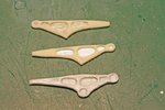
While the two putty bearers were setting up, I started looking at Option 2 which, it appears, may turn out to be better than the putty ones. The picture below shows the two resin bearers, the one having had the lightening holes hollowed out and the other as it has been removed from the mold. As you can see, the one removed from the mold has the lightening holes on the inside and the outer face is completely flat. Removing and replacing the bearings on this one and adding a piece of card to the other may result in an acceptable bearer.

111105 Resin Bearers.jpg


We'll see. In the meantime, I moved on to work some more on the engine parts and cowl. The resin cast lifting eyes on the block were removed and replaced with copper wire and the resin oil thermometers were glued to each side. On the underside of the gear box can be seen an added lube pipe that I had to scratch build as the orginal resin casting broke here.

111105 Engine.jpg


Next we have the annular oil tank. Although only one engine block is supplied by CMK, they supplied two oil tanks, both of which do not extend far enough around the gear box. In the picture below, the as-supplied part is shown at top right. I made the second piece sacrificial, having cut it in half and away from the back plate to supplement the other piece.

111106 Oil Tank 1.jpg


The finished tank with the added bits and the seams hidden with furnace duct tape.

111106 Oil Tank 2.jpg


Next it was on to the lower engine cowl. After having dry fit the engine into position, it became evident that the inner surface of much of the lower cowl in front of the oil cooler would be visible, so some detailing would be necessary. The locating pins and the ejector pin mark would have to be removed and ribs added.

111105 Cowl Before.jpg


The finished lower cowl with added ribs made of card and sprue is shown below. The rear edge of the cowl was also thinned down with my Dremel tool.

111105 Cowl After.jpg


Finally, the resin side panels are added. However, these are not perfect in terms of fit and I may remove these in favour of cutting up the kit-supplied upper cowl. Need to check into that.

111106 Cowl.jpg
 
Last edited:
Two part epoxy putty or Milliput doesn't matter Andy. Always a such parts need a kind of stringers. Usually using of a brassy wire is enough.

A nice job so far. :thumbright:
 
Tough luck Karl. Ironically, after having looked for this one for along time and finally winning it on E-Bay, I saw one at a local swap just 2 months ago.
 
Looks fantastic Andy. Even if you go with the modified resin parts, I'd be interested in seeing haw the putty parts came out. I would never thought of trying that.
 
Last edited:
Sure thing Glenn. Here's a comparison pic. Two uppers are the modified resin and the lower is the best of the putty trial. More details will be added yet around the bearings to finish these up. The putty piece actually has the more correct shape, though. Note the rounded profile around the bottom bearing housing whereas the resin ones are pointy at this location.
 

Attachments

  • 111107 Bearer Comparison.jpg
    111107 Bearer Comparison.jpg
    91.4 KB · Views: 77
Those engine bearers are beginning to look great yes! Best be careful when you start working on those sidepanels though so you don't wreck your modified supercharger that you put so much effort in. Perhaps reworking the the kit parts has the advantage of better fit (because they're kit parts and hopefully require less work in terms of fit, thus less risk of damaging the surrounding parts)
 
Gerry, nice to see you back and thanks for your interest.

Jelmer, yes, you're correct. If you look closely at one of the pics you can see that I nicked the intake a bit. However, studying some recent photos, I may have made these a bit long anyway. We'll see. I did end up discarding the resin side panels and cut the kit cowl to better ensure a good fit. The resin cowl did not mate well so decided to go this route. As a matter of fact, I found the kit side panels to be of better quality than the resin parts so I got the double bonus for this decision.
 
Great stuff Andy, those bearers look bril!
Have you thought about using your putty bearer to make a plasticine or silicone mould, and then mould them from resin yourself?
 
No, Terry, the putty is actually quite hard and strong so I don't see the value in casting a resin bit. Fact is, the experiment went OK but the result was just not quite to my liking. Once detailed more, the modified resin ones will suffice methinks.
 
OK mate, just a thought. Just been looking at a 'sand bag wall' I made about 18 months ago, in 1/48th scale, using Milliput, and it's as hard as rock - would need a lump hammer to break it !
 

Users who are viewing this thread

Back