look forward to it Andy!
Navigation
Install the app
How to install the app on iOS
Follow along with the video below to see how to install our site as a web app on your home screen.
Note: This feature may not be available in some browsers.
More options
You are using an out of date browser. It may not display this or other websites correctly.
You should upgrade or use an alternative browser.
You should upgrade or use an alternative browser.
1/48 Me 410A-1/U-2 Dietrich Puttfarken - Me/FW Group Build
- Thread starter Crimea_River
- Start date
Ad: This forum contains affiliate links to products on Amazon and eBay. More information in Terms and rules
More options
Who Replied?- Thread starter
- #342
Crimea_River
Marshal
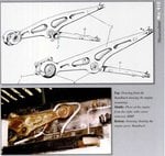
I'm not convince the bearers are curved yet. Been trying to track down some definitive pics.
am off work tomorrow Andy, will look through what i've got and see if anything turns up for you, if you can wait till then that is mate
Aaron Brooks Wolters
Brigadier General
Andy, this is looking spectacular! Excellent work sir, keep it up!!


Airframes
Benevolens Magister
No problem Andy. Seems strange that they would be curved, as they are 'straight' on the '109 and '110. I would have thought that any curve could possibly create inherent weakness to torque effects.
- Thread starter
- #346
Crimea_River
Marshal
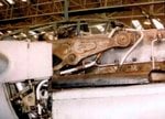
The best pics I've found appear in the Mushroom series book and there does not seem to be a curve. I think Chuk at the other site may have erred here. Looks like I have what I need, thanks guys. The only odd thing is the lightening holes on the line drawing go roight through the bearer whereas the pic shows this to be just a hollow.
Attachments
Airframes
Benevolens Magister
Look closely - the lighting is making things look 'flat'. The lightening holes show the wiring and engine block beyond the 'holes', so the drawing is correct.
- Thread starter
- #348
Crimea_River
Marshal
Airframes
Benevolens Magister
Oops! You're right! My excuse is I had the wrong reading glasses - honest !
- Thread starter
- #350
Crimea_River
Marshal
You've been looking for colour pics of the model that other guy is building...
Jesus...don't start that over here too....

vikingBerserker
Lieutenant General

Njaco
The Pop-Tart Whisperer
looks solid to me - no holes.
- Thread starter
- #354
Crimea_River
Marshal
Yup, solid it will be. Debating how I'll do this now, either built up plastic card or, which I'm leaning toward, making it out of Milliput. I've not had much time for this project lately but hope to get back at it this weekend.
Just wondering why you lean towards making it out of Milliput? Thinking about how I would go about this, wouldn't making it out of plastic card be a much more easy way? Cut out two profiles of the mounts, one with (to depict the depressions in the mounts) and one without holes (to form the solid piece of the mount) and glue these on top of each other? Maybe sand it as necessary to thin it down to scale and and make for some smooth joins (putty and nail polish remover or Mr. Surfacer and Mr. Color Thinner)
Last edited:
- Thread starter
- #356
Crimea_River
Marshal
That's the other option and I may yet go that route. Cutting the lightening holes and bearing sockets in such a small piece of card will be tricky but not impossible.
- Thread starter
- #358
Crimea_River
Marshal
Too much brute force on such a delicate bit. My thoughts on the milliput are that the holes and depressions could simply be pressed in. We'll see how it goes. I have tomorrow off and it's supposed to rain/snow - a good day to devote to this project methinks.
- Thread starter
- #360
Crimea_River
Marshal
Here's my attempt at the first engine bearer:
Started by cutting a template from card and sketching in the bearing housings and lightening holes

Next, I made some dies in the shape of the lightening holes for pressing into the putty. The bearing housings will be pressed in with the end of the yellow plastic swab stick.

The rough bearer is shown below as it is to set overnight. I actually tried Tamiya Putty for this one as opposed to Milliput since I had some laying around. Hopefully I'll get it off the matt without breaking it.

Turned out not too bad. Once it's hard, I'll need to give it a file and sand to see how it finishes up. I still have the option of making one out of card or using the original resin pieces with a bit of fixing. Maybe I'll try all 3 methods and pick the best one. Thanks for looking in.
Started by cutting a template from card and sketching in the bearing housings and lightening holes
Next, I made some dies in the shape of the lightening holes for pressing into the putty. The bearing housings will be pressed in with the end of the yellow plastic swab stick.
The rough bearer is shown below as it is to set overnight. I actually tried Tamiya Putty for this one as opposed to Milliput since I had some laying around. Hopefully I'll get it off the matt without breaking it.
Turned out not too bad. Once it's hard, I'll need to give it a file and sand to see how it finishes up. I still have the option of making one out of card or using the original resin pieces with a bit of fixing. Maybe I'll try all 3 methods and pick the best one. Thanks for looking in.
Users who are viewing this thread
Total: 1 (members: 0, guests: 1)


