parsifal
Colonel
I enjoyed my first build so much I decided to launch into my second. In this build I wanted to
1) learn how to use the air brush
2) undertake modifications to the standard kit
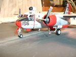
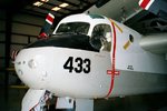
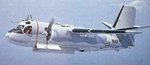
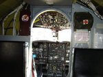
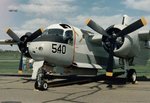
The kit is Hasegawa 1/72 S2F-1 is US livery, dating back to 1970. The kit is okay, but is not perfect for the purposes I want to achieve. As an F-1 it has slightly different dimensions to the E/G models used by the RAN. The cockpit interior is poor,, in that it does not fit well, and is completely lacking in any details at all of the aft crew spaces. The F-1 has some kind of array over the cockpit, which is just not there in RAN aircraft. The MAD probe is not shown.
After some thought I decided to give it a go and undertake some modification to the kit to more accurately reflect the aircraft in RAN service. Wildcat very kindly directed me to a an aftermarket decals kit and paint scheme that I have ordered and should arrive this week some time.
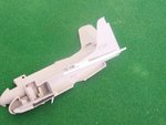
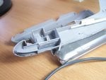
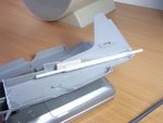
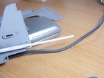
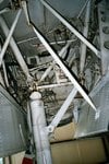
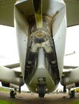
The mods I am going to attempt include cutting the passageway leading from the cockpit to the crew area. I will install decking and some basic depiction of this interior. They will be fairly rudimentary because you wont see much of them, and I am going to have enough trouble doing this without over-complication the interior detailing. I am going to plate over and putty the hole for the forward array that I have not seen in photos of the RAN aircraft. I am going to install a better depiction of the MAD probe, that wil be retractable. The underside surface radome will also be retractable.
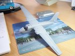
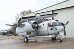
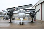
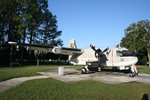
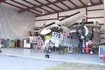
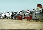
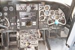
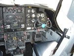
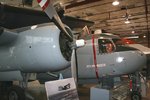
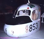
After some serious scratching around the internet, I finally found some interior shots of the bird
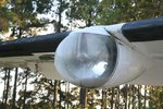
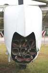
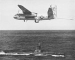
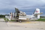
So here goes. First a series of shots showing some of the photographic records that I have found...
1) learn how to use the air brush
2) undertake modifications to the standard kit
The kit is Hasegawa 1/72 S2F-1 is US livery, dating back to 1970. The kit is okay, but is not perfect for the purposes I want to achieve. As an F-1 it has slightly different dimensions to the E/G models used by the RAN. The cockpit interior is poor,, in that it does not fit well, and is completely lacking in any details at all of the aft crew spaces. The F-1 has some kind of array over the cockpit, which is just not there in RAN aircraft. The MAD probe is not shown.
After some thought I decided to give it a go and undertake some modification to the kit to more accurately reflect the aircraft in RAN service. Wildcat very kindly directed me to a an aftermarket decals kit and paint scheme that I have ordered and should arrive this week some time.
The mods I am going to attempt include cutting the passageway leading from the cockpit to the crew area. I will install decking and some basic depiction of this interior. They will be fairly rudimentary because you wont see much of them, and I am going to have enough trouble doing this without over-complication the interior detailing. I am going to plate over and putty the hole for the forward array that I have not seen in photos of the RAN aircraft. I am going to install a better depiction of the MAD probe, that wil be retractable. The underside surface radome will also be retractable.
After some serious scratching around the internet, I finally found some interior shots of the bird
So here goes. First a series of shots showing some of the photographic records that I have found...
![816-10[1].jpg](/forum/data/attachments/99/99245-3e8f8b7b4c216ede597b6a563409cf8b.jpg)
![816-14[1].jpg](/forum/data/attachments/99/99246-8c1930493febcef0ea196b05f7cc9376.jpg)
![3251183785_9bb45bfc21_o[1].jpg](/forum/data/attachments/99/99248-7dec2cd7f7eb898b2701b195925a769e.jpg)
![3251186909_e3fda847ed_o[1].jpg](/forum/data/attachments/99/99249-6bbafeec4c992a99ab7d55402f1966d2.jpg)
![ME_N12_152333a[1].jpg](/forum/data/attachments/99/99254-e1d87df67096cc434c13bd87703ab9e5.jpg)
![Grumman_S_2G_Tracker_1_RAN_VH_NVX_N12_152333_844_Nowra_5_10_86[1].jpg](/forum/data/attachments/99/99253-d7a99e59c910edbb1e121cb876b38fa8.jpg)
![DC_N12_151646[1].jpg](/forum/data/attachments/99/99252-35fc3992c1817a05ba6a7fc023681c7f.jpg)
![3252010956_9d2856f9a0_o[1].jpg](/forum/data/attachments/99/99251-81d88eaf0d2a6b9b3ee4ea4f996f3307.jpg)
![3251483935_5ab1159eb2_o[1].jpg](/forum/data/attachments/99/99250-8f59302af52582e6018c0021d587940d.jpg)
![N12_153566_13_09_2009_11[1].jpg](/forum/data/attachments/99/99259-443221323ea202884fb6a62e61c96d37.jpg)
![N12_153566_13_09_2009_9[1].jpg](/forum/data/attachments/99/99258-9ff6e2c581b839f1439bf465b86d4cdd.jpg)
![N12_153566_13_09_2009_6[1].jpg](/forum/data/attachments/99/99257-2a0b1d95e94a51f1044889b07fed0735.jpg)
![N12_153566_13_09_2009_5[1].jpg](/forum/data/attachments/99/99256-45232cad03b5e4995e9b493fa090d755.jpg)
![N12_153566_13_09_2009_4[1].jpg](/forum/data/attachments/99/99255-829482dc4fccd677bf46c25089c00b1b.jpg)
![track2[1].jpg](/forum/data/attachments/99/99260-965e8bc911368ae061154e5e7ebe98ed.jpg)
![track3[1].jpg](/forum/data/attachments/99/99261-daadc86950c80090c639014352c961f8.jpg)
![tracker[1].jpg](/forum/data/attachments/99/99262-a4ec2d60a91bfe7bdf4bd14c67fb6610.jpg)
![usn45[1].jpg](/forum/data/attachments/99/99263-0c0fe95295232bf46dad33c003e22cd5.jpg)