****DONE: 1/32nd scale Beaufighter VIF, 46 Sqn RAF, Egypt 1943 Group Build

Ad: This forum contains affiliate links to products on Amazon and eBay. More information in Terms and rules

Hopefully, I might have made some progress by tonight. If not, you'll hear some very loud cursing drifting across the Atlantic......

Sounds like fun, not. Trying to catch up on every thing as over time is done for a while for me so if you need something let me know. I may be able find somthing though I dont know much about this aircraft.
 
Thanks Paul. I think I've got most of what I need, but, as stuff on MTO Beaus is somewhat limited, anything you find could prove useful. I've spent ages looking at everything I can find for the MTO squadrons, but most of the pics either can't be positively identified, or are of earlier Mk1 Beaus. Not surprising, as 46 Squadron were hopping about all over the Med on intruder and night fighter ops, so not that many (confirmed) pics of their kites. Some of the external equipment fit is hit and miss also, such as the Beam Approach antenna, normally on the starboard underside. It's on the ETO Beaus, but not on most of the MTO ones, but then, I doubt there were such luxuries on the average desert strip!
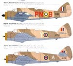
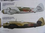
What is really frustrating are colour profiles, such as the one I'm working from, which are detailed and precisely annotated, but no pic to go with them! So where did the artist get the details from??!!!
 
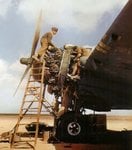
Hi Terry, found some of these that might interest you. I hope :oops:
 

Attachments

  • 1.JPG
    1.JPG
    54.2 KB · Views: 107
  • 2.JPG
    2.JPG
    43 KB · Views: 108
  • 3.JPG
    3.JPG
    64.4 KB · Views: 106
  • 4.JPG
    4.JPG
    54.6 KB · Views: 104
  • 5.JPG
    5.JPG
    33.5 KB · Views: 103
  • 6.JPG
    6.JPG
    16.1 KB · Views: 109
  • 7.JPG
    7.JPG
    126.7 KB · Views: 107
  • 8.JPG
    8.JPG
    62.6 KB · Views: 105
Last edited:
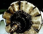
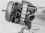
Bl**dy fantastic Paul!! That third colour pic, showing the engine, is exactly what I need right now! It's worth it's weight in Guinness, let alone gold! I can now see which way the inlets go to each cylinder, and the route of the exhaust pipes to the collector ring, plus a lot of other small details not clear in other pics I've found - brilliant! Thanks very much indeed Paul!
 
Bl**dy fantastic Paul!! That third colour pic, showing the engine, is exactly what I need right now! It's worth it's weight in Guinness, let alone gold! I can now see which way the inlets go to each cylinder, and the route of the exhaust pipes to the collector ring, plus a lot of other small details not clear in other pics I've found - brilliant! Thanks very much indeed Paul!

Your welcome though that was kinda just an extra as I though you might like it for the staining on the wing, a few more engine shots.
 

Attachments

  • 2.JPG
    2.JPG
    51.6 KB · Views: 100
  • 1.JPG
    1.JPG
    139.3 KB · Views: 102
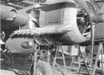
Since I know how accurate you want to be I found the Pneumatics's for you also. I forgot I had part of a manual for this aircraft. :oops:
 

Attachments

  • Beaufighter 396.jpg
    Beaufighter 396.jpg
    209 KB · Views: 99
Last edited:
Once again, brilliant Paul! I've got the first shot, showing the starboard engine, but the last shot is extremely useful. Not sure I'll go as detailed as needing the pneumatics though!! On the pic of the 'bare' engine, those two discs, on each side of the cylinders at front centre, are covering the exhaust outlets. Most kits I've seen of the Beau, including the Tamiya 1/48th scale, and the Revell 1/32nd I'm using now, have them moulded onto the engine parts. I reckon the kit designers must have based the parts on static display engines! I took a shot of a Hercules engine at Duxford, which I've been using, and wondered where the ignition leads were, and the exhaust ports, as everything was capped off. The first shot above I've used, plus another similar pic , which gave me a clue as to where things went, but that colour pic, and the last pic are the business! The colour pics showing the staining and paint wear will also be very, very useful when the time comes!
Thanks very much again mate!
 
Some great stuff there Paul! Love those desert shots. Terry looking forward to pics of your progress on the engine innards 8)
 
I think that's it Paul. I managed to get some detail shots of the Beau under restoration at Duxford, so I've got the landing gear and so on, and the rest of the kite is fairly plain. So I think I'm about there! Unless you have a pic of V8052 of 46 Squadron, as per the attached profile !!
Ooops! forgot to re-size it! This should be a bit smaller!!
 

Attachments

  • Copy of Beau Profile desert NF.jpg
    Copy of Beau Profile desert NF.jpg
    71.5 KB · Views: 101
Last edited:
I think that's it Paul. I managed to get some detail shots of the Beau under restoration at Duxford, so I've got the landing gear and so on, and the rest of the kite is fairly plain. So I think I'm about there! Unless you have a pic of V8052 of 46 Squadron, as per the attached profile !!
Ooops! forgot to re-size it! This should be a bit smaller!!

Humm, that might be a tough one Terry. Will see what I can find :D
 
Nioce shot Paul! As you say, pics of 46 Sqn Beaus are rather scarce. I have found some, but earlier Mk1's, or later MkVI's with the AI MkVIII radar in the thimble nose as you've posted. Ah well, not to worry! Thanks for trying mate.
 
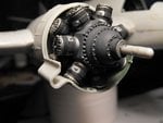
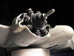
Well, with the aid of Paul's excellent pics, I've been able to plan and commence the installation of the starboard engine, so that the upper cowlings can be left off, and the engine displayed, as if for servicing.
The actual engine bay and/or engines in the kit aren't quite to scale, so the spacing between the rear cylinder bank and the firewall won't be exactly as it should be, but it should look good enogh - fingers crossed.
It took a little over four hours to paint and assemble the engine, then complete the first stage of the installation, not counting time allowed for paint drying and cement setting.
After much test fitting, I decided it would be best to fit the engine to the firewall, then add the exhaust pipes, ignition wires etc.
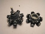
PIC 1 shows the two cylinder banks, the one on the right being the rear bank, with the back facing the camera.
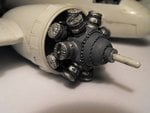
PIC 2 is the first stage of the installation, with the engine assembled and cemented to the firewall. The cooling gill ring has been fitted first, after sawing through the 'joints' and bending up each flap slightly. There should be thin strips covering the gap between each joint, and these will be added later, from thin plastic card, after the main work has been completed and the ring cleaned up. The 'bare metal' rectangles on the front of each cylinder are the exhaust ports, and have only been roughly painted. The scratch-built exhaust pipes will be glued to each of these in turn, with the rear cylinder's pipes joining on to those from the corresponding front cylinder, before joining the exhaust collector ring, which forms the front cowl.
PICS 3 and 4 show the lower cowling panel in place, with the modified exhaust manifold attached. Once this has fully set, the front edge of the cowling panel will be used as a datum against which the exhaust pipes will be measured. Each pipe has to bend up from the respetive cylinder, before bending again to run forward, joining the pipes from the front cylinder, then curving slightly towards rhe inner rear of the collector ring. This job is going to be a little tricky, as I'll need to 'guesstimate' where and how to cut each pipe, at the right angle, so that they can attach to the collector ring on the inside! I haven't quite figured out exactly how I'm going to glue them, but I've got a few ideas!
Once that little job is out of the way, twin igntion wires will be made , and glued into holes already drilled into the plug seats in each cylinder head. the wires will curve down behind each cylinder, then run back to the ignition harness, which surrounds the rear of the engine, against the firewall.The latter will be made from wire, whilst the ignition leads themselves will be made from stretched sprue. The inlet pipes to each cylinder will also be made from stretched sprue, whilst any brackets or cowling frames will be fabricated from thin plastic strip.
When all this has been done, the final painting will be completed on the engine, then the whole lot masked, in preparation for the first stage of the main colour scheme paintwork.
That's the plan anyway!
 

Attachments

  • MTO Build 314.jpg
    MTO Build 314.jpg
    44.3 KB · Views: 120
  • MTO Build 316.jpg
    MTO Build 316.jpg
    43.9 KB · Views: 120
  • MTO Build 320.jpg
    MTO Build 320.jpg
    44.8 KB · Views: 122
  • MTO Build 323.jpg
    MTO Build 323.jpg
    41 KB · Views: 115

Users who are viewing this thread

Back