keen to see more Terry!
Navigation
Install the app
How to install the app on iOS
Follow along with the video below to see how to install our site as a web app on your home screen.
Note: This feature may not be available in some browsers.
More options
You are using an out of date browser. It may not display this or other websites correctly.
You should upgrade or use an alternative browser.
You should upgrade or use an alternative browser.
****DONE: 1/32nd scale Beaufighter VIF, 46 Sqn RAF, Egypt 1943 Group Build
- Thread starter Airframes
- Start date
Ad: This forum contains affiliate links to products on Amazon and eBay. More information in Terms and rules
More options
Who Replied?Vic Balshaw
Major General
Can't wait till sunrise, Oz time


- Thread starter
- #203
Airframes
Benevolens Magister
Sorry guys, got a bit behind on this one - too many other things going on!
I hope to have some more pics a bit later tonight (UK) time. I've had to do some planning and measuring in order to display one engine, as just leaving off a cowling panel would look b*ll*cks. So, it needs a bit more scratch-building of engine mounts, cowling supports and plumbing etc, which is going to take a bit of time. I'll at least get a pic of the other engine though, the one which will be cowled!
I hope to have some more pics a bit later tonight (UK) time. I've had to do some planning and measuring in order to display one engine, as just leaving off a cowling panel would look b*ll*cks. So, it needs a bit more scratch-building of engine mounts, cowling supports and plumbing etc, which is going to take a bit of time. I'll at least get a pic of the other engine though, the one which will be cowled!
- Thread starter
- #204
Airframes
Benevolens Magister
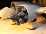
As promised, here's some progress shots of the engine which will be hidden under the cowlings and the large exhaust collector ring.
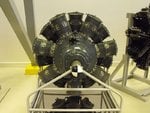
PIC 1 is a shot of the real thing. As you can see, the front end is rather plain, all the ignition harness and other ancilliaries being at the rear. The Bristol Hercules was a sleeve-valved engine (hence the whistling sound which gave rise to the name 'Whispering Death'), so there are no exposed pushrods or valve covers.
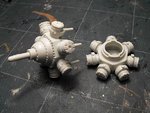
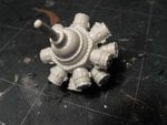
PICS 2 and 3show the two cylinder banks assembled, and both test fitted, to check alignment.
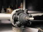
PIC 4 The port engine has been painted and fitted to the firewall. It needs a bit of retouching here and there after handling, as the darned thing refused to bed down and set! There won't be any additions made to this engine, except a scratch built cowling support ring and stays, as the lump will be buried in the close-fitting cowlings, and masked by the deep exhaust collector ring and the huge propellor. However, the starboard engine will recieve some scratch-built detailing, as two of the cowling panels will be left off. Tthis will involve making some cowling support frames, the engine mounts, ignition harness and some 'plumbing' etc.
PIC 5. The one-piece cooling gills had to befitted before the engine was glued in place, and they looked a bit plain. The rear outer rim was thinned down, then the gills themselves cut through with a razor saw, and bent upwards slightly. They are in the process of being cleaned up in this shot.
So far, building one engine, and planning and measuring up for the fitting of the other one, has taken about five hours, so there's not much more to show at the moment. With a bit of luck, I should get some more work done over the weekend, and hopefully move on to the initial painting stages. Still a heck of a lot of other detail work to do though, as the landing gear and the entrance and escape harthes need attending to yet.
Thanks again for your interest.
Attachments
Vic Balshaw
Major General
A true master, very nice.


109ROAMING
2nd Lieutenant
Good work mate , looks great
Heinz
Captain
Great stuff Terry!
B-17engineer
Colonel
LOL I thought the engine was yours in picture one I was like, wow some modeling reference 
lesofprimus
Brigadier General
Hot sh!t Terry, lookin choice my man....
kgambit
Tech Sergeant
Awesome job on the engines Terry. 
very nice mate !
- Thread starter
- #214
Airframes
Benevolens Magister
Thanks guys, but it's only a bit of paint, needing re-touching too! The other engine will receive the attention !
vikingBerserker
Lieutenant General
DAM!!
Excellent Terry!
- Thread starter
- #218
Airframes
Benevolens Magister
Thanks guys!
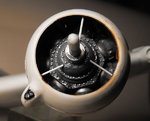
I've got the port engine and cowling squared away, and the intial work done for the flame-damper exhausts. The starboard engine is under construction, and will have the ignition leads added, plus a few other bits, although I'm still undecided whether to leave off one of the cowling panels. The kit parts are designed to be removable, but I found when constructing the port engine, that the cowlings actually brace the exhaust collector ring, which, in effect, is the nose-ring cowl.
I've worked out a way of building the whole assembly without the top cowlings, and this will also mean making and fitting a cowling attachment frame, which is rather thin and narrow, But, if I can cut some thin aluminium litho plate, I should be able to make the framework to scale - I hope!
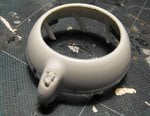
PIC 1 shows the exhaust collector ring (the front cowl) as supplied in the kit. This is more or less correct for the Mk1, but the MkVIF had breather pipes in the front of the exhaust manifold outlet, the bulge on the left in the picture.
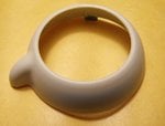
PIC 2 The front of the outlet was cut and sanded flat, then drilled and trimmed to obtain a rounded, rectangular opening. The twin breathers were made by drilling-out some 'Evergreen' rod, as I didn't have any suitable tube, cutting to the required length, and glueing in place. Sorry the pic is a bit 'soft'.
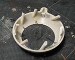
PIC 3. The exhaust pipes for the rear cylinder bank were added to the inside of the exhaust collector ring. These were made by cutting some plastic tube at an angle, then cementing at the required pitch, in order to match the exhaust outlets on each of the seven rear cylinders. This will need to be much more precise for the starboard engine, if the top cowlings are omitted!
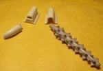
PIC 4. On the left are the kit parts for the exhaust outlet manifold, and the short exhaust pipe. As the MkVIF night fighter had 'porcupine' flame damper exhausts, the parts had to be modified to accept the 'Quickboost' resin flame dampers, as shown on the right in the pic.
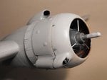
PIC 5 With the exhaust collector ring and cowlings in place and set, support stays were added, made from stretched sprue, and set at the correct asymetric angles. These have yet to be painted, and some other retouching done around the engine crank case.
PIC 6. Shows the exhaust outlet and manifold, awaiting the 'porcupine' exhaust. This will be fitted after the model has been painted, and a support bracket added between the rear of the flame damper and the underside of the wing leading edge.
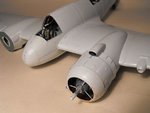
PIC 7 This is how the model looks to date, with the port cowlings in place, and the carb air intake fitted.
Once the starboard engine, ancilliaries and cowlings have been done, it'll be time to fit some of the smaller bits and pieces, before continuing to sand off the cockpit canopy framing, polish it and fit it, ready for the first stage of painting. The Observers hatch opening will be masked, and the landing gear fitted after the model is painted, decalled and matt coated.
Then it's on to the detail parts, including the entrance hatch covers and steps, the observers hatch cover, and the cockpit roof hatch. Still a long way to go yet!
Thanks again for your interest and kind comments.
Attachments
Last edited:
109ROAMING
2nd Lieutenant
Sounds good though!
Vic Balshaw
Major General
No pics, you've got me hanging Terry


Users who are viewing this thread
Total: 1 (members: 0, guests: 1)

