Airframes
Benevolens Magister
Scale; 1/32nd.
Kit: Revell Beaugighter Mk1 converted to MkVIF Night Fighter.
Category: Judge
Here we go then, to start off the third ww2aircraft.net Group Build, a conversion from the Revell Beaufighter Mk1 to the MkVIF Night Fighter. First, a little background to the subjsect.
Number 46 squadron was formed at Wyton, Cambridgshire, UK, in April 1916, and saw action right through WW1, before disbanding in 1919.
The squadron reformed in September 1936, with Gloster Gauntlets, before re-equipping with Hurricanes in February 1939. These aircraft were used during the Battle of Britain from September 1940. The Squadron moved to Malta in May 1941, supposedly equipped with Hurricane MkIIs, but the pilots were absorbed by 261 Squadron, with the ground crews acting as a maintenance unit until May 1942, when the Squadron moved to Idku, Egypt, to be again absorbed, this time as a detachment of 89 Squadron, with Beaufighters.
The MkVI Beau was received soon after, and 46 Squadron commenced operations as a night fighter unit, and provided cover over coastal shipping and over Egypt. In August 1943, detachments of the squadron were based at various locations around the Eastern Mediterannean, as intruder missions took place over the Greek islands, and fighter cover was also provided. Although the Squadron received some Mosquitoes in July 1944, it is thought that these saw little action, as the squadron returned to the UK in December.
The model will be based on a MkVIF operating from Iduku in the summer of 1943, and there are a number of changes required to model this version from the old Revell kit. This rather large kit was first released in the early 1970's, and the simplicity of design, common for the era, is evident throughout. However, although simple, and totally inaccurate internally, the overall shape and dimensions are fine, and I hope to be able to do justice to what can be a nice model, if a bit on the big side!
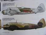
PICS 1 and 2. The colour profile (from SAMI Beaufighter book, via Jan) shows the desert scheme, with the night fighter black undersides extending up the fuselage sides, which I think will make for an interesting, and rather different, subject. Also visible in the profile are the tailplanes which, on this version, wwere changed from the horizontal type of the earlier Beaus, to a sharp dihedral, in order to improve stability and control. These will need to be altered from the kit parts, and I'm still working on a way to do it without too much major surgery being involved!
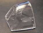
The external areas of the kit aren't too bad, and the required radar antennas are included, but there are certain parts which will need attention, apart from the tailplanes, in order to model the MkVI. This includes the cockpit canopy, which is moulded as a veary early type, with the horizontal frames on the quarter lights and the port side screen.
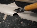
PIC 3 Shows work under way to remove the frames, and I just hope that the area can be successfully polished back to full clarity. If not, it'll either mean replacing the side panel, or moulding a new canopy. Once fitted, the roof hatch will be posed open.
The internal fittings and moulded 'detail' are totally incorrect, with the forward bulkhead in the wrong place by a good eight scale feet or so, and a non-existant bulkhead in the rear fuselage observer's position.
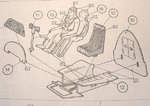
PICS 4 and 5shows the kit instruction drawings for these areas.
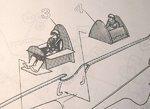
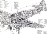
PIC 6 is a cutaway if a MkIF, which had drum-fed cannon, as opposed to the belt-fed guns of the MkVIF. The internal arrangement however is similar, and shows the correct possition for the armoured bulkhead and it's open doors.
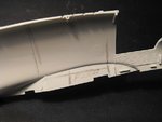
PIC 7 The kit does not provide any internal detail or flooring, apart from the two individual modules already shown. As the model will have the front and rear cockpit hatches open, and also both belly access hatches, the internal areas will need to be scratch-built. These will include the cockpit, using the kit parts as a basis to work with, the observer/radar operators position, and the centre section, which housed the cannon's four ammunition tanks positioned above angled cut-outs in the floor.
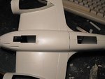
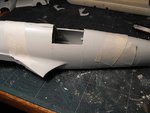
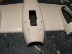
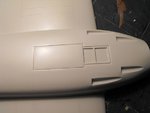
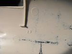
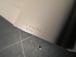
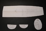
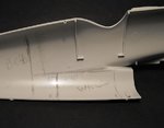
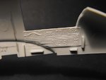
PICS 8 to 10 show the pencilled marks where the flooring, bulkheads and access hatch wells will be built, together with the paper templates produced, which will be used as patterns to cut the basic shapes required from plastic card. These will then be shaped and cut-outs made where neccessary, and fitted to the fuselage before being detailed with scratch-built additions.
So, once I get the PTO Build Avenger finished, and the Spit XIV finalised, I'll be making a start on this big beastie.
Watch this space!
NOTE:- Due to my stupid fingers selecting the wrong pic, I've removed PIC 2 , re-sized it, and it's now the last pic!! This meansd the numbering is now totally b*ll*xed!
Kit: Revell Beaugighter Mk1 converted to MkVIF Night Fighter.
Category: Judge
Here we go then, to start off the third ww2aircraft.net Group Build, a conversion from the Revell Beaufighter Mk1 to the MkVIF Night Fighter. First, a little background to the subjsect.
Number 46 squadron was formed at Wyton, Cambridgshire, UK, in April 1916, and saw action right through WW1, before disbanding in 1919.
The squadron reformed in September 1936, with Gloster Gauntlets, before re-equipping with Hurricanes in February 1939. These aircraft were used during the Battle of Britain from September 1940. The Squadron moved to Malta in May 1941, supposedly equipped with Hurricane MkIIs, but the pilots were absorbed by 261 Squadron, with the ground crews acting as a maintenance unit until May 1942, when the Squadron moved to Idku, Egypt, to be again absorbed, this time as a detachment of 89 Squadron, with Beaufighters.
The MkVI Beau was received soon after, and 46 Squadron commenced operations as a night fighter unit, and provided cover over coastal shipping and over Egypt. In August 1943, detachments of the squadron were based at various locations around the Eastern Mediterannean, as intruder missions took place over the Greek islands, and fighter cover was also provided. Although the Squadron received some Mosquitoes in July 1944, it is thought that these saw little action, as the squadron returned to the UK in December.
The model will be based on a MkVIF operating from Iduku in the summer of 1943, and there are a number of changes required to model this version from the old Revell kit. This rather large kit was first released in the early 1970's, and the simplicity of design, common for the era, is evident throughout. However, although simple, and totally inaccurate internally, the overall shape and dimensions are fine, and I hope to be able to do justice to what can be a nice model, if a bit on the big side!
PICS 1 and 2. The colour profile (from SAMI Beaufighter book, via Jan) shows the desert scheme, with the night fighter black undersides extending up the fuselage sides, which I think will make for an interesting, and rather different, subject. Also visible in the profile are the tailplanes which, on this version, wwere changed from the horizontal type of the earlier Beaus, to a sharp dihedral, in order to improve stability and control. These will need to be altered from the kit parts, and I'm still working on a way to do it without too much major surgery being involved!
The external areas of the kit aren't too bad, and the required radar antennas are included, but there are certain parts which will need attention, apart from the tailplanes, in order to model the MkVI. This includes the cockpit canopy, which is moulded as a veary early type, with the horizontal frames on the quarter lights and the port side screen.
PIC 3 Shows work under way to remove the frames, and I just hope that the area can be successfully polished back to full clarity. If not, it'll either mean replacing the side panel, or moulding a new canopy. Once fitted, the roof hatch will be posed open.
The internal fittings and moulded 'detail' are totally incorrect, with the forward bulkhead in the wrong place by a good eight scale feet or so, and a non-existant bulkhead in the rear fuselage observer's position.
PICS 4 and 5shows the kit instruction drawings for these areas.
PIC 6 is a cutaway if a MkIF, which had drum-fed cannon, as opposed to the belt-fed guns of the MkVIF. The internal arrangement however is similar, and shows the correct possition for the armoured bulkhead and it's open doors.
PIC 7 The kit does not provide any internal detail or flooring, apart from the two individual modules already shown. As the model will have the front and rear cockpit hatches open, and also both belly access hatches, the internal areas will need to be scratch-built. These will include the cockpit, using the kit parts as a basis to work with, the observer/radar operators position, and the centre section, which housed the cannon's four ammunition tanks positioned above angled cut-outs in the floor.
PICS 8 to 10 show the pencilled marks where the flooring, bulkheads and access hatch wells will be built, together with the paper templates produced, which will be used as patterns to cut the basic shapes required from plastic card. These will then be shaped and cut-outs made where neccessary, and fitted to the fuselage before being detailed with scratch-built additions.
So, once I get the PTO Build Avenger finished, and the Spit XIV finalised, I'll be making a start on this big beastie.
Watch this space!
NOTE:- Due to my stupid fingers selecting the wrong pic, I've removed PIC 2 , re-sized it, and it's now the last pic!! This meansd the numbering is now totally b*ll*xed!
Attachments
-
 MTO Build.jpg54 KB · Views: 579
 -
 MTO Build 002.jpg41.3 KB · Views: 543
 -
 MTO Build 011.jpg59.8 KB · Views: 543
 -
 MTO Build 012.jpg48.4 KB · Views: 529
 -
 MTO Build 005.jpg26.5 KB · Views: 511
 -
 MTO Build 007.jpg36.8 KB · Views: 511
 -
 MTO Build 006.jpg24.8 KB · Views: 526
 -
 MTO Build 008.jpg33.1 KB · Views: 536
 -
 MTO Build 014.jpg85 KB · Views: 618
 -
 Beau Profile desert NF.jpg86.1 KB · Views: 650
Last edited by a moderator: