****DONE: 1/32nd scale Beaufighter VIF, 46 Sqn RAF, Egypt 1943 Group Build

Ad: This forum contains affiliate links to products on Amazon and eBay. More information in Terms and rules

Great stuff Terry!

In regards to your knife you are using what type is it exactly? I'm curious to try some of this 'modding' lark in my models but my craft knifes are a bit iffy for precise cuts.

Cheers.
 
Thanks very much guys, and you're right Dan, the whole thing is going to be a little bit of a challenge!
Alex, my normal knife is a Swann Morton surgical scalpel, with No.10 blades for a straight cut, and occassionally the rounded blade. If you mean the tool in the picture, that's a razor saw, as Wojtek uses. This one was very kindly sent to me by Matt, and is absolutely fantastic! I don't know how I ever managed without one! The blades are like 'old fashioned' razor blades, with very, very fine teeth of different gauges, two gauges per blade, and there are spacer bars so that multiple blades can be fitted for parrallel cuts. It can be used with normal razor blades also, but I haven't needed those yet. It's great for 'engraving' panel lines too.
The company mine came from is in the 'States, and here's the details:-
Unique Master Models (UMM U.S.A.)
UMM-USA Unique Master Models
Hope this helps.
Terry.
 
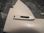
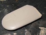
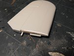
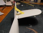
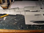
Well it looks like I've solved the minor problem of setting the previously horizontal tailplanes at a 12 degree dihedral. The simplest solutions are often the best, so I simply enlarged the slots for the tailplane locating tabs, added a small plastic rod to each 'plane, and drilled an angled hole at the rear of the tailplane fuselage root for the rod to fit into. The underside of each tailplane was then packed out with plastic card, which was then trimmed and sanded flush with the 'planes surface.
PIC 1 Shows the enlarged slot and angled hole on the starboard side.
PIC 2 The plastic card packing on the underside of one of the tailplanes.
PIC 3 The packing trimmed and roughly sanded.
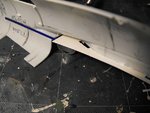
PIC 4. Test-fitting the port tailplane. The small gap on the underside will be filled and blended in once the units are cemented in place and set.
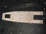
With that job taken care off, and the tailplanes put aside until required, work on the interior fittings has commenced. The previously made cardboard template for the floor was used to mark-out and cut a basic floot panel from 1mm plastic card.
This was manouevred into the taped-together fuselage and checked for fit, with any trimming being carried out as required.
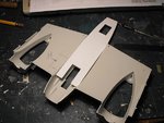
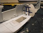
Once satisfied, the floor was carefully aligned in the correct position on the outside of the fuselage, and the positions of the entrance hatches checked. These had already been marked in pencil, being half the length of the external apertures. The latter will have their forward sections plated-over internally, to form recesses where the hatch covers would sit when closed. The apertures for the floor hatches were then carefully cut out. (The hatches on the Beau pivot at their centre point, opening upwards and inwards, and form a baffle against the slipstream for parachute exits.)
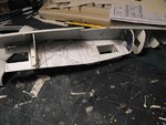
PIC 5 shows the blank floor panel test fitted to the bottom centre section. The floor will be fitted into one fuselage half, and the entrance hatches will have the wells boxed to align with the external apertures. The forward hatch will be a bit tricky, as the centre section can't be fitted until later, so the floor will be mated to the rear of the cockpit tub, and the well box built around it.
PIC 6 Both fuselage halves, and the lower centre section, have been marked out to show the position of the floor, bulkheads, main frames and the front spar. Plastic strip will be glued along the fuselage walls, to support the floor. Once the floor is in position, and checked for fit on the opposite side, the fuselage former frames, longerons and stringers will be made and added, before the interior is fitted out with the bulkheads and equipment.
PIC 7. The floor panel has been marked out to indicate where the open sections need to be cut out, and where the bulkheads, frames, main spar and observers seat frame will fit. The main floor panel will have the support framework added, and the main supports underneath glued once the whole lot is in position and set.
Most recent photos of restored Beaufighters, in paricular the Duxford-based aircraft, have shown a plywood floor over the metal framework, the floor panels, in a sort of diamond shape, being left in bare wood. However, some of the pictures I've seen of operational Beaus suggest that the floor was either metal covered in parts, or the wood was painted. As a compromise, I intend to paint all the 'metal' areas, and give the 'wooden' part a scuffed look, as if it had been painted, but the wood is showing through. But, that's a long way off yet!
So, the next stage is to fit the floor, and construct the entrance hatch wells, before moving on to the fuselage framework and bulkheads.
More soon folks!
 

Attachments

  • MTO Build 037.jpg
    MTO Build 037.jpg
    38.8 KB · Views: 190
  • MTO Build 043.jpg
    MTO Build 043.jpg
    51.1 KB · Views: 191
  • MTO Build 042.jpg
    MTO Build 042.jpg
    56.9 KB · Views: 181
  • MTO Build 045.jpg
    MTO Build 045.jpg
    52.7 KB · Views: 163
  • MTO Build 049.jpg
    MTO Build 049.jpg
    58.2 KB · Views: 191
  • MTO Build 052.jpg
    MTO Build 052.jpg
    64.3 KB · Views: 192
  • MTO Build 051.jpg
    MTO Build 051.jpg
    64.2 KB · Views: 182
Thanks Keith and VB.
Work is continuing on scratch-building the interior, with the main floor and bulkheads in place, and the rear entrance well boxed in.
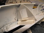
PIC 1 In order to support the floor, plastic strip was cemented along the sides of the fuselage halves. Where the wing root curves outwards, a 'shelf' of plastic was added, with cut-outs to allow the wing centre-section locating lugs to fit.
When these had set, the floor was glued into place , in the starboard fuselage half.
PIC 2. The equipment frame, rear bulkheads, and the flare chute were added. The frame and bulkheads were cut from plastic sheet, with strip added to the frame, and the flare chute was made from a length of 'Evergreen' plastic tubing.
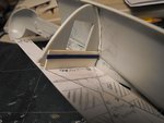
PICS 3 and 4. The front, armoured bulkhead from the kit was cut to fit, and added to the floor. Plastic card and strip has been used to provide the bracing, and to build up the internal section of the wing main spar, with a step added on the door ledge. This has all yet to be trimmed and cleaned up, and the armoured doors will added later, in the open position.
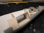
PIC 5. The rear entrance well has been boxed in, with 'lightening' holes drilled into the rear wall.
PIC 6. This is how she looks so far on the inside, with the floor and bulkheads, and the rear entrance well in place.
The next step is to make and add all the fuselage frames and the longerons and stringers. When these are set, the main equipment framework and racking will be built and added, and then the whole area will be sprayed in Cockpit Green, before adding the 'wood' sections to the floor. After that, it's time to work on the cockpit and front entrance well, part of the latter being assembled inside the lower centre - section. Only part of the cockpit 'tub' will be used, with the rest being scratch-built, including the framework, seat and instrument panel. Then, it's the long job of adding all the internal fittings and detial to the main fuselage.
I might just get this done by the end of the GB!!
Thanks again for your interest and positive comments.
Terry.
 

Attachments

  • MTO Build 054.jpg
    MTO Build 054.jpg
    55.4 KB · Views: 188
  • MTO Build 059.jpg
    MTO Build 059.jpg
    53.3 KB · Views: 156
  • MTO Build 060.jpg
    MTO Build 060.jpg
    45.6 KB · Views: 164
  • MTO Build 061.jpg
    MTO Build 061.jpg
    44.8 KB · Views: 178
  • MTO Build 066.jpg
    MTO Build 066.jpg
    40.5 KB · Views: 157
  • MTO Build 064.jpg
    MTO Build 064.jpg
    69.9 KB · Views: 174

Users who are viewing this thread

Back