109ROAMING
2nd Lieutenant
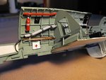
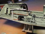
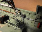
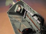
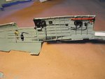
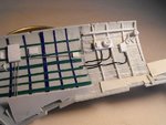
looks like a lotta hard work but the result is superb!
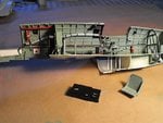
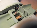
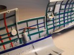
Great stuff mate! 8)
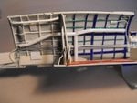
Great stuff mate! 8)
Follow along with the video below to see how to install our site as a web app on your home screen.
Note: This feature may not be available in some browsers.
Ad: This forum contains affiliate links to products on Amazon and eBay. More information in Terms and rules
")