**** DONE: 1/48 ICM Spitfire Mk IX AE-B Ian Keltie of 402 SQDN RCAF Commonwealth GB

Ad: This forum contains affiliate links to products on Amazon and eBay. More information in Terms and rules

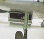
Thanks Wojtek, Terry. The evidence for a single tube mounts but it makes me wonder why they would have just installed this for one side. I wonder if the de-icing fluid comes from the same tank as the windscreen de-icer and whether the intent was for emgergencies only.

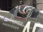
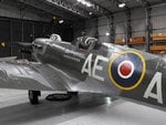
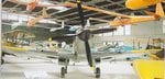
Pics below are from the Topshots book on the Mk XVI and show why I think the tube is slightly off center.
 

Attachments

  • Mk XVI Nose On.jpg
    Mk XVI Nose On.jpg
    102.7 KB · Views: 151
  • Mk XVI Rad Zoom.jpg
    Mk XVI Rad Zoom.jpg
    42.8 KB · Views: 142
Looks like you're right Andy!
I've scoured every pic I can of the MkVIII, MkIX and MkXVI, checked the pilot's Notes, and even looked at the works schematic drawings of the cooling system. With regard to the pics, I was looking mainly for period shots, just in case a currently preserved example had a tube removed for whatever reason - and I could find no really clear, conclusive shots to show a tube existed in the port rad bath.
However, the schematics show that the port bath contains the coolant radiator mounted in the inboard section, with the oil cooler taking up the remaining space (approximately 1/3rd) outboard. The starboard bath is similar, with the smaller inter-cooler radiator inboard. The de-icer pipe appears to be only just off-centre, by about 2 or 3 inches (50mm to 75mm) to outboard, in the starboard bath only.
It does seem strange to have a de-icer in one rad bath only, although perhaps the port side gun-heating system might have something to do with this?
Certainly on the Mk19, and AFAIK, the MkXIV, both baths had the de-icer pipes, but then, of course, they were a much larger area.
Hope this helps.
 
Good job you mentioned it Andy - I was going to put one in both baths, until I started checking !
Just noticed I need to add a couple of things to mine, including a small intake below the windscreen on the port side. (not on the MkIX.)
 
Much of the work that's been done since the last update has been filling, sanding, an scribing done over several stages. With the fuselage ready for a prime coat, I had to get the canopies in place and therefore complete some of the internal details as shown on the following pics.

The results of the filling work at the port wing root and rear fillet are shown here. The cockpit hatch is temporary to prevent paint going into the pit and is the piece that I had previously cut out. It's glued back in with carpenter's glue for ease of removal. Also seen is the hole I drilled at the wing leading edge for the fuel cooler.

101217 Wing Root.jpg


Next up, despite what I said before, I did fabricate the longitudinal frame under the rear canopy. Unfortunately, as I suspected, it was a bit tall for the canopy so I had to remove part of it to install the glazing after this shot was taken.

101217 Rear Canopy Rail.jpg


The next two pics are of the gunsight that I modified from the kit part. The kit part is made from clear plastic and the reflector glass scales to about 2 inches thick. I therefore cut off the kit reflector glass and the lower piece of the molding to make the sight appear like the Mk I sight used in the Mk IX Spit. I replaced the reflector with a piece of clear plastic from some packaging and made the mounted from card and sprue - rather difficult to see in the next pic. The pic below shows the kit part (from my Mk VIII kit) and the finished modified piece next to it. The range dials were created by cutting a slot with my razor saw and, once the part was painted black, the numbers on the dials were simulated with white paint scratched with a needle. I'm kind of stoked how this turned out.

101217 Gun Sight Half Done.jpg

101217 Gun Sight.jpg


As stated earlier, I had bought an Ultracast resin prop when I got the resin seat pair so I set about assembling this today. I first washed the parts and unfortunately when drying them I broke the tip off one of the extremely thin blades. After luckily finding the broken tip on my kitchen counter, I carefully glued it back on with CA glue and sanded it smooth. You can just see the fracture line on the prop closest to the camera in this picture. I hope it doesn't break again because it's a major pain to glue this on. To make sure the prop blades were correcty aligned, I lined them up on the grid lines of my cutting mat and used a spacer gauge to ensure the blades were in plane. The pitch was adjusted by eye and each blade was glued in with CA individually.

101217 Prop Building.jpg


The final pic shows the the last prop blade installed and curing as well as an overall shot of the model with the canopy parts having just been installed. I'll allow this to set over night and will then apply a primer coat tomorrow after masking the canopy.

101217 Overall.jpg


Thanks for your continued interest.
 
Beautiful bit of workmanship on the port wing root Andy and as for the gunsight, you should be wrapped with that, its brilliantly made.

Like your use of woodworkers glue as a temporary fixer, must remember that for temp jobs. I'd have stuffed a little bit of foam into it................:p
 
Thanks Wayne.

Below are some details of the primed model showing some additional finish work needed. Pardon the dust on the finish - I really need to build myself a spray booth. This will be given a light sanding before refinishing.

First up is an overall shot with primer on. Again, don't worry about the pilot's hatch as it's temporary.

101219 Overall Primed.jpg


Next is a close-up of the right side of the canopy. A bit of filling is still needed where the windscreen meets the fuselage. This being a clear part, it was hard to see without the primer. If you look closely, there's also a very shallow vertical sink mark on the fuselage jusy below the windscreen.

101219 Winscreen Fill.jpg


The port wing fillet also needs a bit more work to sand down the bumps. Using primer to see these imperfections is a real benefit as can be seen here.

101219 Wing Fillet.jpg


Finally, here's a shot of the rad de-icer tube with I only installed on the starboard side.

101219 Rad De Icer.jpg


Scheduled today is the above repair work, touch up paint, and, if I'm lucky, I'll start painting the sky band and yellow wing leading edges.
 
Looking rather good there Andy. The windscreen base (on the side panels) only really needs a tiny weeny touch of filler, probably a thin bead of PVA, at the extreme forward end, where the side screen meets the windscreen frame base. Unlike the earlier screen, when the internal armoured glass was fitted, the side screens had a thin metal fillet along the base, and the joint from roughly the mid-point to the rear vertical frame, where it deepened in a sort of triangular shape, was more noticeable. In fact, this often became rather 'weathered', with paint wear and chipping, particularly on the port side, where hands held when leaning into, or getting into and out of the cockpit.
I'll try to find some close up shots to show what I mean.
 
Here you go Andy. This is one of the Duxford Spits, in a colour scheme I'm sure you'll recognise, and shows the fillet, or trim, quite well.
 

Attachments

  • Czech 046.jpg
    Czech 046.jpg
    98.3 KB · Views: 161
Nice work Andy, I'm sure you will be able to sort these irritations out and some nice close clear pictures.
 

Users who are viewing this thread

Back