Looking good so far!
Navigation
Install the app
How to install the app on iOS
Follow along with the video below to see how to install our site as a web app on your home screen.
Note: This feature may not be available in some browsers.
More options
You are using an out of date browser. It may not display this or other websites correctly.
You should upgrade or use an alternative browser.
You should upgrade or use an alternative browser.
**** DONE: 1/72 Westland SeaKing - Home Country Modern Aircraft/Spitfire Marks GB
- Thread starter parsifal
- Start date
Ad: This forum contains affiliate links to products on Amazon and eBay. More information in Terms and rules
More options
Who Replied?brucejscott
Staff Sergeant
Looks great Michael! Getting close to done.
Crimea_River
Marshal
Agree. Looks pretty good.
- Thread starter
- #104
parsifal
Colonel
Ive been messing about on the workbench, trying to find a way to make these tie downs. The two sides are different. The port side is a relatively short line that is connected to the fuselage at two points, one just aft of the cokpit glazing, looping under the hull to a ring just in front of the underside landing light assembly. Vic covered this pretty well in his build, but mine will need to be about half the diameter for the underside connecting ring.
On the starboard side, there is a longer line that runs from just under the cockpit assembly to a point underneath the starboard sponson. I am still unsure how that connection takes place, at either end of this line. The Photographs that I do have appear to show the uppeer connection as going into the hull itself ie there are no fasterners outside of the hull. I dont know whats holding the line below the sponson.
I can use 8amp fuse wire to create my metal fasteners, if and when I find that detail (if anyone has that information it would be appreciated). I am not sure how to simulate the line however. The port side line is simply plastic nylon rope (Orange of all colours!), but Im not sure what the starbord side line is. not even sure its rope. Its a different colour and a slightly different texture. Not thjat I am all that worried about that.
I think the best way to recreate this line is to paint and use 10lb BS fishing line. It seems to be the right thickness, but any advice would be most welcome guys.....
Vic Balshaw
Major General
It's looking good Michael and the area of that rotor span is huge, it's one aspect where I think storage may be a problem.
Not sure if this is going to help but in regards to the underbelly sling, there are four anchor points, two port and two starboard. In addition there is also a cable coming out from the cockpit on the starboard side which I believe is the electrics for operating the hook clamp/release. From the port side just to the rear of the second sort of recess area a second cable comes out within a protective tube and runs under the belly where it is again the cable is connected to the underside through a tube before it also connects to the slink hook. I believe that this is a device in which they hoist the whole hook assembly up to the belly so that when not in use, it is not slapping on the ground.
Not sure if this is going to help but in regards to the underbelly sling, there are four anchor points, two port and two starboard. In addition there is also a cable coming out from the cockpit on the starboard side which I believe is the electrics for operating the hook clamp/release. From the port side just to the rear of the second sort of recess area a second cable comes out within a protective tube and runs under the belly where it is again the cable is connected to the underside through a tube before it also connects to the slink hook. I believe that this is a device in which they hoist the whole hook assembly up to the belly so that when not in use, it is not slapping on the ground.
N4521U
Plastic Pirate
You've got great results mate.
And fabbing the hold downs, doesn't mean you have to put the first ones on. We all do them over and over till they are right. Can't makem look like you wantem, don't usem.
Maybe All of us is a bit of an untruth, but most of us.
I have solved the "storage" problem of the size of the rotors on my HH-60H. I am making a storage rack for them! Simple. My SH-3A will have them in the rack as well, the SH-60B will have them and the tail folded.
Last edited:
- Thread starter
- #107
parsifal
Colonel
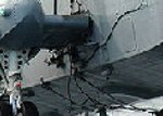
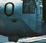
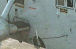
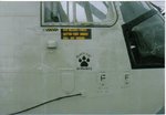
well, ive spent this evening looking at photographs of the tie downs and believe i have enough information to attempt something. The attached images give a bit of a summary of what I have found.
In summary, the 1980s versions of the Sea King had a tie down cable on the port side, with a heavy ring attached to both ends of that cable.. The cabling does not appear Orange to me, it appears dark grey, brown or black.
The cabling on the starboard side is electrical cable. Has a small bracket forward, and larger one under the Sponson. The cables that go under the hull are not evident in the earlier 1980s version....that appear to have been added in the 80s.
So now I have to try and fabricate all of this. I will see how things go.
Attachments


ccheese
Member In Perpetuity
She looks good, Michael.... well done, Mate.
Charles
Charles
A4K
Brigadier General
Yep, great work Michael! (Man, she looks real in that last set of pics! ") )
)
)Vic Balshaw
Major General
Just pulled up a few more photo angle that may help Michael.


Made some good progress Michael, well done!
fubar57
General
Looks great Parsifal.
Geo
Geo
- Thread starter
- #113
parsifal
Colonel
have had some good progress, and a bit of a setback as well. have completed my scratch built tie downs and am very happy with them. have tidied up the paint scheme some more, again fairly succesfully. i have about half the decals on now. i had a lot of trouble with some of the larger transfers, they simply would not release from the backing paper. Luckily I had made copies of the decal sheets, and they came in very handy.
Last night i had a bit of a setback, though it may be a hidden blessing. A light stand fell on the model, doing some damage. The pontoons separated from the fuselage, but nothing was broken. Its given me the opportunity to properly touch up some of the paintwork around the pontoons, particulalry the black trim. i hadnt realized that I had oversprayed some parts a bit, so i now have clear access to rectify that issue....
I should be able to post some meaningful progress shots tomorrow night
Airframes
Benevolens Magister
Sounds like a worthwhile session Michael, looking forward to the pics.
yep, me too...
Vic Balshaw
Major General
Sound like you had a blessing in disguise Michael, looking forward to them progress shots.
brucejscott
Staff Sergeant
Make something good out of it, proper attitude.
meatloaf109
1st Lieutenant
Yep, one I need to keep in mind also.Make something good out of it, proper attitude.
- Thread starter
- #120
parsifal
Colonel
sorry guys for the long delay. I have a fair bit on the plate at the moment, building a house, and a 2 year old terror on the loos. Anyway, finally got a few hours to do some stuff. Have completed most of the repairs, and applied about half the deacls. i completed my scratch built tie downs and am pretty happy. I have a bit more of a problem than i had realized though. The damage the model sustained included sending the tailwheel off into oblivion, which i didnt see the other night. i have built a replacement, and its sort of okay, but i have decided to buy a replacement . A bit wasteful i know, but it was at least cheap ($9) but has to come fom the US which can take a while here in Oz. If it doesnt arrive on time I will have to use the gerry built one.
I showed my son my model collection. Maybe a mad thing to do, but he was pretty good with it. Knew that it was special to me, and not for playing with. i was impressed with his maturity to be honest..
Anyway, here are the progress shots i have been promising for so long. i apologize for the delay
I showed my son my model collection. Maybe a mad thing to do, but he was pretty good with it. Knew that it was special to me, and not for playing with. i was impressed with his maturity to be honest..
Anyway, here are the progress shots i have been promising for so long. i apologize for the delay
Attachments
![000_0332[1].jpg](/forum/data/attachments/185/185398-d0fb167fefc20c2cdcfe7e832620bb8d.jpg)
![000_0333[1].jpg](/forum/data/attachments/185/185399-97132879cd85b460e354368dabec7fd3.jpg)
![000_0334[1].jpg](/forum/data/attachments/185/185400-a5c9c0900c20699d053a8544ff8dc0e7.jpg)
![000_0335[2].jpg](/forum/data/attachments/185/185401-5d888121b6ee09431f9ae92a2de789d6.jpg)
![000_0336[1].jpg](/forum/data/attachments/185/185402-58ab174fd3428fae7f9321bca60ac050.jpg)
Users who are viewing this thread
Total: 1 (members: 0, guests: 1)