Fw-190 Dora-9 vs P-51D Mustang

Ad: This forum contains affiliate links to products on Amazon and eBay. More information in Terms and rules

so Jon what do you think you should do ? ......... Olivier has some excellent materials posted all through the forum(s) listed there on other subject matters

another one might be of use is to look through the listings in www.airwarfareforum.com
 
Thanks Erich :oops: but I don't think I'll join, yet; as for me, I'm still playing here, in these forums, not quite 'setteled in' yet. Besides remembering two screen names, passwords would be taxing... PS > You are correct about the Stuka's markings. I'll fix this soon, thanks again.
 

Attachments

  • timetofly_029_typhoon_early_121.jpg
    timetofly_029_typhoon_early_121.jpg
    17.5 KB · Views: 690
Here is a little more information on the P-51 and some of it's teething and lingering problems. http://yarchive.net/mil/p51.html

As Jon notes all these planes had strong points and weaker points and its the pilot that gets the advantage, and by using his strong points to his opponents weaker points is the winner. The P-51 with numbers and tactics made up for many of its weaker points to do a great job.

wmaxt
 
DerAdlerIstGelandet said:
Does anyone have any kind of info als on the 190D. That would be interesting to see.

Yes Adler, it also seems to me that people have forgotten them. Here they are:

Fw-190D-9 statistics:

Empty weight: 3,490 kg (7,694 lbs)

Fully Loaded weight *Clean*: 4,293 kg (9,464 lbs)

Maximum loaded weight: 4,839 kg (10,670 lbs)

Internal fuel capacity: 524 L + 111 L auxiliary - 635 L total.

Ammunitions weight total: Ca. 145 - 150 kg. (319 - 330 lbs)

Fw-190D-9 dimensions:

Wing span: 10.50 m (34.44 ft)

Wing area: 18.3 m2 (197 sq.ft)

Length: 10.20 m (33.46 ft)

Height: 3.35 m (10.99 ft)

Fw-190D-9 aerodynamic statistics:

Wing aspect ratio: 6.02

Airfoil profile: NACA 23015.3 - NACA 23009

Wing thickness ratio: Root= 15.3% Tip= 9%

Wing Cl-max *Freeflow*: 1.58

Jumo 213A-1 engine power output:

Normal takeoff: 1,755 PS
Takeoff w/ increased boost pressure : 1,900 PS (Start u. Notleistung)
Emergency w/ MW50 and B4: 2,100 PS. (Notleistung mit MW50)
Special emergency w/ MW50 and C3: 2,100 + PS (Sonder Notleistung)
Special emergency w/ Compressor, C3 and MW50: 2240 PS (Sonder Notleistung mit A Lader als Bodenmotor)

Additionally I remember some time ago, a German mechanic who talked about how they could quite easily get 2,300 HP out of the Jumo 213, it only took abit of tinkering with the engine. And these field modifications weren't a rare occurrence, it was done quite often he said. Has anyone else got any info one this ?

______________________________________________________

And about all of those turn charts and so on, well has even a single one of them figured power-loading figures into their calculations ? Cause you know power-loading is a critical factor to how well a plane turns.

The greater the power, the steeper the bank angle an aircraft can turn at a given speed. This is why the FW-190D9 outturns the FW-190A. (Along with the Dora-9's significantly lower body drag ofcause!)

Also the P-51's wing has a CL-max of 1.28 *Freeflow*, at idle that is probably 1.47, while the Fw-190's is probably around 1.80.

There's no doubt what so ever that the Fw-190D-9 will outturn the P-51D, although not by a whole lot, but the Dora-9 does turn tighter nonetheless. The reason being that the Dora-9 has both a lower lift-loading and power-loading, as-well as lighter elevator stick forces at high speeds.

Oscar Boesch from Sturmstaffel 1, also stated that in a very tight and high speed turn the Fw-190 only required one hand on the stick. This allowed the pilot to get a much better feel for what the aircraft was doing, allowing him to fly at the edge of the envelope at all speeds. As a matter of fact, the FW-190 experienced an almost dangerous reduction of stick forces at high speeds. No loss of control, just an increased chance to stress the airframe.

The P-51 however experienced stability issues in dives and compressed at any speed above the POH limits. In fact the P-51 exhibited stability issues in high-speed level flight that were never completely eliminated. Other than that, the Merlin powered P-51's have stall characteristics very similar to the FW-190's but lacks the instant recovery. Typically a P-51 lost 7000-9000 feet in recovery. The source for many P-51 pilots death when stalled at low altitude. It still gets modern P-51 pilots, causing quite a few tragedies: http://www.mustangsmustangs.net/p-51/p51news/shuttleworth.shtml

_____________________________________________________

The Kommandogerät

Soren, there is an extensive American report on the Kommandogerat which says the same as what Lunitic says. http://naca.larc.nasa.gov/reports/1945/naca-wr-e-192/index.cgi?thumbnail1#start

I know Krazi, but those are with an Fw-190A wich has a malfunctioning engine, and since the Kommandogerät controls both engine settings and prop pitch, that effectively renders those tests worthless. And thats not all that was wrong with the Anton tested by the US, the ailerons on that aircraft were badly out of adjustment exhibiting aileron flutter and reversal leading to premature stalling in turns.(It was the same story with Faber's A-3 btw) It is written about in this report as the first peculiarity of the FW-190(Below). And despite having both engine troubles and ill adjusted ailerons leading to premature stalling, the Navy's Fw-190A (Which wasn't a fighter version btw) turned just as well as the light P-47 it was pitted against. (Quite impressive..)

http://www.terra.es/personal2/matias.s/aleirons.jpg

And to answer many people's questions about the Kommandogerat:

No, a pilot could not manage the engine and propeller as well as the Kommandogerät. This is backed up by both allied and Luftwaffe pilots who have flown with the system.

And about the US Navy test pilots who at first disliked the kommandogerat, their reasoning was: "because they felt manual control gave better engine response". Those same pilots who flew those tests reversed their position 60 years later. In their words: "Perhaps we had an overinflated opinion of our abilities".

The Kommandogerat was really an ingenious device, for example if the pilot wanted to dive, all he had to do was to shove the throttle to the firewall and point his nose down. The Kommandogerät adjusted the engine and prop to optimum setting based on real world real time conditions, and all the pilot had to do was to sit back and enjoy the ride.

In the P-51 however, "the pilot had to yank and pull levers working his prop and engine, so as not to burn up a crank bearing by over speeding the prop. The auto function on the CSP simply did not take into account all the environmental factors. It adjusted based off a manifold pressure relationship. The Kommandogerät on the other hand, took into account everything from spark advance to fuel delivery. It did it according to the actual altitude and airspeed as measured by barometric sensors. It was not a "recipe" calculator. Inputs did not happen according to a preset table but rather changed based on real world conditions to optimum performance considering multiple factors. These settings were calibrated at sea level and checked according to a chart by the pilot before takeoff."

Some pictures of this engineering marvel:

kommandogerat1.jpg

kommandogerat2.jpg
 
Great information Soren! I've posted info on that before. In the 1970s Beech Aircraft actually stumbled on this technology and incorporated into its Bonanza (I think around 1975).

Having to manipulate mixture and prop contols is no big thing, and I really think it wouldn't be an issue in combat, even it the pilot only has a few hundered hours. After about 10 or 20 hours of flying in an aircraft with a constant speed propeller, it becomes second nature, but this thing still makes it easier....
 
I will explain as plainly as I can how I arrived at "those turn charts and so on". Thanks for the back-handed remark.

In a sustained turn thrust equals drag. For a prop airplane thrust T = Power / Speed = P/V. Drag D = zero lift drag + lift induced drag. I have P-51D and Fw190D-9 zero lift drag coefficient and Fw190D-9 induced drag coefficients. The 190 came direct from a FW document. I had to estimate the lift induced drag coefficient for the P-51D. We have all we need we have power we have the drag coeficients. We know the L = load factor times weight. So we have all the ingredients. You pick a speed, iterate on load factor until thrust = drag. Simple. Power is in there. Weight is in there. Power loading is accounted for. You take n plug it into the turn rate equation and voila "those turn curves."

To go further I took the power curves, which represents uninstalled power by the way, and analyzed the max level speeds. Again in that situation thrust = drag. I created a set of correlation factors so that I could get from uninstalled power - also accounting for exhaust thrust, you forgot about that, well you probably didn't know about it, again obvious - to installed power correlated to known historic values for speed. I used those correlation factors when doing the turn performance. I have different values for both planes, especially since the P-51D engine power curves don't give exhaust thrust.

Is there another way to go about it?

As far as no doubt about plane A out-turning plane B. I ask that you prove it analytically because I never have found anything that shows a German flight test or aero analysis of turn capability.
 
paul.kachurak said:
I will explain as plainly as I can how I arrived at "those turn charts and so on". Thanks for the back-handed remark.

In a sustained turn thrust equals drag. For a prop airplane thrust T = Power / Speed = P/V. Drag D = zero lift drag + lift induced drag. I have P-51D and Fw190D-9 zero lift drag coefficient and Fw190D-9 induced drag coefficients. The 190 came direct from a FW document. I had to estimate the lift induced drag coefficient for the P-51D. We have all we need we have power we have the drag coeficients. We know the L = load factor times weight. So we have all the ingredients. You pick a speed, iterate on load factor until thrust = drag. Simple. Power is in there. Weight is in there. Power loading is accounted for. You take n plug it into the turn rate equation and voila "those turn curves."

To go further I took the power curves, which represents uninstalled power by the way, and analyzed the max level speeds. Again in that situation thrust = drag. I created a set of correlation factors so that I could get from uninstalled power - also accounting for exhaust thrust, you forgot about that, well you probably didn't know about it, again obvious - to installed power correlated to known historic values for speed. I used those correlation factors when doing the turn performance. I have different values for both planes, especially since the P-51D engine power curves don't give exhaust thrust.

Is there another way to go about it?

As far as no doubt about plane A out-turning plane B. I ask that you prove it analytically because I never have found anything that shows a German flight test or aero analysis of turn capability.

What about bank angle?
 
Several years ago, I read an article in the Smithsonian Air Space magazine about the P51's radiator arrangement. It produced quite some "free thrust" from its design. Wouldnt that boost its speed at a seemingly lower power rating?
 
Bank angle is not part of the equation per se. A plane banks to an angle required by the desired load factor. The key is load factor. Bank angle is found by the arc-cosine of the inverse of load factor or bank angle = acos(1/n). So that means every airplane, every single one, regardless of airfoil, wing design, etc. in order to turn at a load factor of n does it at the same bank angle.

For example to turn at a load factor of 2 the bank angle is 60 degress. Every single airplane from a B-52 to an F-16 to a Cessna 182.

Read this: http://www.pilotsweb.com/principle/load.htm

For those of you so inclined I recommend "Airplane Aerodynamics and Performance" by Jan Roskam. He is a professor at the University of Kansas. I took his class about 9 years ago.
 
paul.kachurak said:
Bank angle is not part of the equation per se. A plane banks to an angle required by the desired load factor. The key is load factor. Bank angle is found by the arc-cosine of the inverse of load factor or bank angle = acos(1/n). So that means every airplane, every single one, regardless of airfoil, wing design, etc. in order to turn at a load factor of n does it at the same bank angle.

For example to turn at a load factor of 2 the bank angle is 60 degress. Every single airplane from a B-52 to an F-16 to a Cessna 182.

Perfect! ;)
 
My view on the Dora remains exactly the same, a great aircfrat, a lethal toy.

Everyone will agree the Luftwaffe endured prohibitive losses in some days during the final weeks of the war.

Erich pointed the fact of high losses, which is correct. Also that British were not impressed with the Dora. I ask, did the British ever admit being impressed by anything the German fielded against them?

Perhaps by the time of the Dora reached service in numbers they were not Erich, for the brunt of the fight was being carried out by the gentlemen of the USAAF. But you bet they were not only impressed, but also shocked -when facing other German weapons- when they were still alone in the fight in the air.

Mr.Soren, I am glad you came along with the information on the flawed test carried out with that Fw 190 A (another flawed testing of German hardware for the allies).

Although I had no technical evidence to back this up, I was sure Mr. Lunatic´s claim of the Kommandogerat entering a "divided by zero error condtion" was not correct. I will explain why a few lines ahead for I have combat evidence which discards that comment.

Not only that, I quote Lunatic´s comment that followed:

"I believe but am not positive that in the Dora there was a bypass to allow manual operation when altitudes exceeded the system capabilities, at around 24,000 feet."

Some examples to substantiate my full confidence on how erroneous the sources of Mr. Lunatic regarding the Kommandogerat issue are:

JG 2 and JG 26 are some of my "specialties". Have many books, articles and printings on both units. The Kanaljäger which pounded the hell of the RAF when they got fitted with the Fw 190 A´s.

Some useful combat data:

I can tell you of a victory of Luftwaffe experten Sigfried Lemke (I./JG 2)over a P-38 above the 7,500 meter level flying precisely a Butcher Bird, attained on May 9th, 1944.

Two more victories of pilots of the Schlageter geschwader, especifically from 1./JG 26, Georg Kiefner and Waldemar Soffing, each shooting down P-51s in the 7,500 meter altitude on May 20th, 1944, flying what? A Butcher Bird.

7,500 meters=24606 feet

Those were only 3 cases of victories over USAAF craft over 24,000 ft for the guys of JG 2 and JG 26 during 1944, but there are several more.

Lunatic said he believes the "capabilities of the system were exceeded" at 24,000 ft; the victories cited here show the assertion is clearly incorrect.

What you are basically suggesting there Lunatic, is that the Germans were stupid people. Have you seen the data sheets of the Fw 190 A´s? What do you think the service ceiling of the Antons was? Certainly not 24,000 ft, but even more.

What about 37,000 feet? That about such altitude would not be a very good fighter is a different tale; what I can assure you is the fact the computer did not entered a "divided by zero error mode".

You are saying the plane -Fw 190 A- was rated to fly at an altitude where the Kommandogerat would for sure get screwed.

Not to mention the fact, that from all the accounts of German pilots who flew the Butcher Bird, not for once I am able to recall anything that might be related to any sort of "problems" with the Kommandogerat.

Now, the service ceiling of the Fw 190 Dora, you bet it came to surpass the Butcher Bird in this particular department.

I digress, the Dora was a clear improvement over his predecessor. Superior high altitude performance for sure.

That the swarms of Mustangs arriving way from above when the Doras were still climbing inflicted them ugly damage is another story. It does not mean the Dora could not more than tangle with the Mustang.
 
Soren said:
Yes Adler, it also seems to me that people have forgotten them. Here they are:

Thanks Soren, but I already have that information. I was talkinga bout stuff like was posted for the P-51 here like on the prohibited manuevers and what not. Even if they are in German, I can translate them.
 
The British were impressed with the Dora, possibly a 13, which flew a mock combat with a Tempest V, Udet. :shock:

Service ceiling is not FTH, which, for the A-8 was ~6000m. The FTH of the Dora was not much more than that.

Service ceiling of the Dora 9 was 10.7km which is 1.9km lower than the Dog Pony's. FTH of the Dog Pony was 1.0km higher than the Dora's 6.6km.

Lt Ossenkop of I./JG26, on the P-51: "the two a/c were about equal in normal combat, which was an advantage for us comapred to the A-8. The Mustang was faster in a dive."

Compared to the Anton 9, the Dora was not much better, if any. Many Anton 8s got the A-9's motor.

The Kommandogerat of the Antons was not the same Kommandogerat as used in the Doras.
 
Flyboy... I gotta love ya! Your one line questions during my table construction were great; you have not lost your 'touch'. You beat me to the punch. Bank angle is one question, tail distance from CG is another; I have more but, let's look at bank angle.
paul.kachurak answered you by saying (wrap-up) it has nothing to do with turn rate. paul.kachurak I'm surprised at you, Flyboy I'm disappointed in your acceptance of paul's answer, when 1 page ago, out of the '51s flight manual is a bank angle chart. paul.kachurak, If I were to tell you I would be performing a series of 'load factor of 2' turns, I would only be telling you of my 'feeling' during the occurrence, my acceleration; I would be describing nothing about my turn radius, my 'airspeed'. Bank angles greatly effect turn performance, as your speed, turn rate angle of attack react with the 'fixed' optimal bank angle for any given wing loading. In other words, if paul.kachurak were correct, turn data would be readily available, as we all know it is not, both paul I have had to calculate it. Anyway what paul refers, known bank values for any given loading, is shown below for some common angles...

Bank angle___Cosine_____W/S increase [g] ______Vs1 multiplier
_10°_________0.98_______1.02___________________1.01
_20°_________0.94_______1.06___________________1.03
_30°_________0.87_______1.15___________________1.07
_40°_________0.77_______1.30___________________1.14
_45°_________0.71_______1.41*__________________1.19
_50°_________0.64_______1.56___________________1.25
_60°_________0.50_______2.00___________________1.41*
_70°_________0.34_______2.94___________________1.71
_75°_________0.25_______4.00___________________2.00


My understanding of the forces of a turn… Sorry for the length…

When an aircraft is airborne at a constant velocity altitude the load on that aircraft's wings is the aircraft's mass, expressed as being equivalent to '1g'. When the aircraft is parked on the ground the load on the aircraft wheels is a 1g load.

Any time an aircraft's velocity is changed there are positive or negative accelerative forces applied to the aircraft. The resultant maneuvering "load factor" is normally measured in terms of "g" load which is the ratio of the forces experienced during the acceleration to the forces existing at 1g.

Describing a '2g turn' or by saying "I pulled 2gs"; what is being implied is that during the maneuver a 'radial' acceleration was applied to the airframe the load on the wings doubled. This is 'radial g', or centripetal force. It applies whether the aircraft is changing direction in the horizontal plane, the vertical plane, everything between.

It is conventional to describe g as positive when the loading on the wing is in the 'normal' direction. When the load direction is 'reversed' it is described as negative g. Negative g can occur momentarily in severe turbulence but an aircraft experiencing a sustained 1g negative loading is flying in 'equilibrium', but upside down, such as during an 'outside' loop (i.e. the pilot's head is on the outside of the loop rather than the inside) when the aircraft will be experiencing various negative g values all the way around the maneuver.

The structures of the aircraft we are concerned with are required to withstand in-flight load factors not less than +5g to –3g at COMBAT WEIGHT without any malformation – temporary or otherwise. In addition, to allow for less than optimum craftsmanship, a 'design safety factor' of, at the time, 1g was added typically, thus the aircraft should normally cope with load factors of +6g to –4g.

It should not be thought that aircraft structures are significantly weaker in the negative g direction. Remember the normal load is +1g, not 0g.

When an aircraft turns, an additional force must be continuously applied to overcome inertia, as inertia's normal tendency is to continue in a straight line; this is achieved by applying a force towards the centre of the curve or arc, the centripetal force, which is the product of the aircraft mass and the 'overcoming' acceleration required. Remember that acceleration is the rate of change of either speed or direction or both. The acceleration, as you know from driving a car through an S curve, depends on the speed at which the vehicle is moving around the arc and the radius of the turn. At a slow speed in a sweeping turn there is very little acceleration, holding the turn is easy, but at high speed, holding a small radius involves high acceleration with consequent high radial g or centripetal force that makes it difficult to hold the turn.

The acceleration towards the centre of the turn is V²/r meters per second per second and the centripetal force required to produce the turn is m × V²/r newtons where r is the turn radius in meters and m is the aircraft mass in kilograms. Remember we are using aircraft mass not weight.

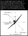
Please refer to the illustration below...

In a level turn the vertical component of the lift [Lvc] balances aircraft weight and the horizontal component of lift [Lhc] provides the centripetal force.
An aircraft's mass is 400 kg. In a 250 meter radius horizontal turn at a constant speed of 97 knots or 50 m/s:-

Centripetal acceleration = V² / r = 50 × 50 / 250 = 10 m/s²
Centripetal force required = m × V² / r = m ×10 = 400 × 10 = 4000 newtons
The centripetal force of 4000 N is provided by the horizontal component of the lift force, from the wings when banked at an angle from the horizontal, the correct bank angle being dependent on the velocity and radius: much like a motorbike taking a curve in the road. During the level turn the lift force must also have a vertical component to balance the aircraft's weight, in this case also 4000 newtons. But the total required force is not 4000 + 4000 N, rather we have to find the one, and only one, bank angle where Lvc is equal to the weight and Lhc is equal to the required centripetal force.
What then will be the correct bank angle [ø] for a balanced turn? If you have access to trigonometrical tables (I use Jerry's Beckwith's spreadsheet tables) this is easy, if not...
In a level turn requiring 4000 N centripetal force with weight 4000 N the tangent of the bank angle = 4000/4000 = 1.0 and thus the angle = 45°. Actually the bank angle would be 45° for any aircraft of any weight moving at 97 knots in a turn radius of 250 metres provided the aircraft can safely fly at that speed, bank angle. Now what total lift force will the wings need to provide in our level turn if the weight component is 4000 N and the radial component also 4000 N?

Resultant total lift force = weight divided by the cosine of the bank angle or L = W / cos ø. Weight is 4000 N, cosine 45° is 0.707 = 4000/0.707 = 5660 N.
So the load on the structure – the wing loading – in the turn, is 5660/4000 = 1.41 times normal or 1.41g.
We know that lift = CL × ½rV² × S = Weight
thus W = CL × ½rV² × S
or W / S = CL × ½rV² = the wing loading

From this we can see that if wing loading increases in a constant speed maneuver then CL, the angle of attack, must increase. Conversely if CL , the angle of attack, is increased during a constant speed maneuver the lift, and consequently the wing loading, must increase. Now this is where paul.kachurak, I believe, gets this stuff confused...

It can be a little misleading using terms such as 1.41g or 'load factor of 1.41'. For instance if an aircraft has a mass of 340 kg and if you do the preceding centripetal force calculation using that mass you will find that the centripetal acceleration is 10 m/s², centripetal force is 3400 N, weight is 3400 N and total lift = 4800 N, i.e. the actual wing loading is 20% less but it is still a 1.41g turn, i.e. 4800/3400 = 1.41.

Thus rather than thinking in terms of g equivalents, it may be more appropriate to consider the actual loads being applied to the aircraft structures, and the norm is to use the wing loading as the primary structural load reference.

Aircraft designed with higher wing loading are usually more maneuverable, are less affected by atmospheric turbulence, but have higher minimum speed than aircraft with lower wing loading. Wing loading is usually stated in pounds per square foot.

How does an aircraft increase lift if it maintains the same cruise speed in the level turn? Well the only value in the equation - Lift = CL × ½rV² × S - that can then be changed is the lift coefficient, which must be increased by the pilot increasing the angle of attack. Note that increasing AoA will also increase induced drag, so that the pilot must also increase thrust to maintain the same airspeed; thus the maximum rate of turn for an aircraft will also be limited by the amount of additional power available to overcome induced drag.

For a level turn the slowest possible speed and the steepest possible bank angle will provide both the smallest radius and the fastest rate of turn, but there are limitations...

If you consider an aerobatic aircraft weighing 10 000 N and making a turn in the vertical plane, i.e. the loop described earlier, and imagine that the centripetal acceleration is 2g; what will be the wing loading at various points of the turn? Actually the centripetal acceleration varies all the way around because the airspeed and radius must vary but we will ignore that and say that it is 2g all round. If the acceleration is 2g then the centripetal force must be 20000 N all the way round.

A turn in the vertical plane differs from a horizontal turn in that, at both sides of the loop, the wings do not have to provide any lift component to counter weight, just lift for the centripetal force, so the total load at those points is 20 000 N or 2g. At the top, with the aircraft inverted, the weight is directed towards the centre of the turn and provides 10 000 N of the centripetal force and the wings need provide only 10 000 N. Thus the total load is only 10 000 N or 1g, whereas at the bottom of a continuing turn the wings provide all the centripetal force plus counter the weight, so the load there is 30 000 N or 3g.

This highlights an important point: when acceleration loads are reinforced by the acceleration of gravity, the total load can be very high.

If you have difficulty in conceiving the centripetal force loading on the wings, think about it in terms of the reaction momentum, centrifugal force which, from within the aircraft, is seen as a force pushing the vehicle and its occupants to the outside of the turn; lift (centripetal force) is counteracting it. Centrifugal force is always expressed as g multiples.
 

Attachments

  • timetofly_015_jjgscfs_2_p_38lo_avg_625.jpg
    timetofly_015_jjgscfs_2_p_38lo_avg_625.jpg
    20.2 KB · Views: 440
  • jjgs_turn_ill_155.jpg
    jjgs_turn_ill_155.jpg
    46.8 KB · Views: 505
...As for other things:

I didn't even know about 'Kommandogerat' before I became a member here. So far as I can tell, I would have to agree with the postings that tell of it's outstanding ability, as opposed to it having a fatal flaw; as I agree about not having ever read about it's failure. Great postings by the way.

Indeed under certain conditions, the installation of the radiator on the P-51 provided positive thrust, not enough to wright a letter home to mama, but it signifies that its installation caused little, very little drag.
 

Attachments

  • jjgs_cfs_2_time_to_fly_rev2_000_haileyg_593.jpg
    jjgs_cfs_2_time_to_fly_rev2_000_haileyg_593.jpg
    20.6 KB · Views: 397
JonJGoldberg said:
Flyboy... I gotta love ya! Your one line questions during my table construction were great; you have not lost your 'touch'. You beat me to the punch. Bank angle is one question, tail distance from CG is another; I have more but, let's look at bank angle.
paul.kachurak answered you by saying (wrap-up) it has nothing to do with turn rate. paul.kachurak I'm surprised at you, Flyboy I'm disappointed in your acceptance of paul's answer.
Thanks John, but I quickly accepted his answer becuase for the most part he was correct and showed that bank angle table...

load03.jpg


load01.jpg


What I was looking for was the statement "at a load factor of 2 the bank angle is 60 degress. Every single airplane from a B-52 to an F-16 to a Cessna 182." Now with that 60 degree 2G bank, start discussing the actual turn radius for the given aircraft - that I haven't seen here....

The site also showed "the formula"

l_formula.jpg


I think we're all saying the same thing, but the real "mea"t here is to show 30-45 degree bank angles turns at say 10,000 feet at say 300 knots, I'd like to see a chart like that comparing these aircraft...
 
...To put it much much more simply, a desired turn (turn rate) has a load factor that affixes a bank angle. I've not seen anyone approach turning by looking at a load factor as the turn solutions point of origin, nor is it a number that is not relevant in the comparison of two aircraft's turning performance. For example the FW-190 is stressed to, memory now, I'm not looking it up right at the moment, 9 g, where the P-51 is rated for 8 g. We should be able to conclude that the FW-190 easily outperforms the 51, as it is able to maintain higher bank angles, load factors, and now from here turn performance (data) can be assessed based on airframe stress values alone. I do not agree with this approach.
 

Attachments

  • timetofly_002_jjgscfs_2_p_51d_haileyg2_110.jpg
    timetofly_002_jjgscfs_2_p_51d_haileyg2_110.jpg
    19.6 KB · Views: 401
[quote="FLYBOYJI think we're all saying the same thing, but the real "mea"t here is to show 30-45 degree bank angles turns at say 10,000 feet at say 300 knots, I'd like to see a chart like that comparing these aircraft...[/quote]

Here is a site that has a table showing turn rates and times. I think some parameters were assumed (such as a 9g limit) so that all aircraft would be compared on an equal basis.
http://www.rdrop.com/users/hoofj/corner
There are other charts to but I'm not sure if these were derived to incorporate into a sim or taken, at least partialy, from a sim.

wmaxt
 

Users who are viewing this thread

Back