- Thread starter
- #281
Hello, Ari. Your CAD work is very nice.
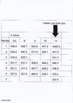
Let me indicate the rail location X-Y as the stringer No.11 from the fuselage center lines.
Y values were indicated in the Mitsubishi A6M5 drawing No.1204 for the stringer location.
X values were read from the same drawing.
Frame Nos./X as half width/Y as height (unit:mm)
No.1/ 352.4/ 541.2
No.2/ 351.6/ 550.0
No.3/ 341.4/ 543.0
No.4/ 340.0/ 536.2 (Read value as indicated it is straight between No.3 and 6)
No.5/ 336.8/ 530.4 (Read value as indicated it is straight between No.3 and 6)
No.6/ 333.2/ 524.0
No.7/ 322.8/ 510.2
There were three wheels with equal interval on one side.
The first wheel, for example, moved from frame No.3 to No.5.
In this case, the width difference was only 4.6mm and it would be similar for the rest of the wheels.
I think there was enough space for the wheels to slide inside the rail track.
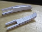
Your last photo was taken by Taizo Nakamura aka A6M232.


