P-47D RAZORBACK, 1/48 Monogram " DONE! "

Ad: This forum contains affiliate links to products on Amazon and eBay. More information in Terms and rules

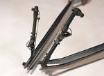
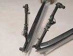
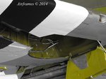
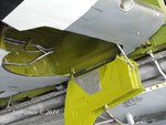
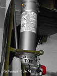
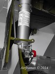
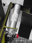
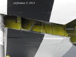
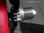
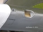
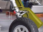
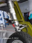
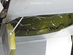
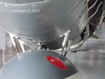
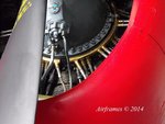
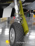
Here's the rest of the pics, and the retraction rod is clearly visible in those showing the landing gear.
I'm afraid I still can't get my PDF writer to work, and I can't seem to save and file pics from books on my computer either - looks like I'll have to get my mate, who did the up-dates, added extra storage and memory etc, to have a look after the holidays, as the relevant programmes are installed, but the computer can't 'find' them when requested to do so !
Anyway, I hope these help, and have a great Christmas.
 

Attachments

  • D Day DX Fuji 056.jpg
    D Day DX Fuji 056.jpg
    82 KB · Views: 115
  • D Day DX Fuji 057.jpg
    D Day DX Fuji 057.jpg
    92.7 KB · Views: 109
  • D Day DX Fuji 058.jpg
    D Day DX Fuji 058.jpg
    97.3 KB · Views: 120
  • D Day DX Fuji 059.jpg
    D Day DX Fuji 059.jpg
    62.9 KB · Views: 125
  • D Day DX Fuji 060.jpg
    D Day DX Fuji 060.jpg
    56.6 KB · Views: 115
  • D Day DX Fuji 061.jpg
    D Day DX Fuji 061.jpg
    72.9 KB · Views: 116
  • D Day DX Fuji 062.jpg
    D Day DX Fuji 062.jpg
    80.9 KB · Views: 123
  • D Day DX Fuji 063.jpg
    D Day DX Fuji 063.jpg
    71.5 KB · Views: 116
  • D Day DX Fuji 064.jpg
    D Day DX Fuji 064.jpg
    67.2 KB · Views: 108
  • D Day DX Fuji 065.jpg
    D Day DX Fuji 065.jpg
    123 KB · Views: 127
  • D Day DX Fuji 066.jpg
    D Day DX Fuji 066.jpg
    64.5 KB · Views: 115
  • D Day DX Fuji 067.jpg
    D Day DX Fuji 067.jpg
    91.6 KB · Views: 116
  • D Day DX Fuji 068.jpg
    D Day DX Fuji 068.jpg
    106.1 KB · Views: 113
  • D Day DX Fuji 069.jpg
    D Day DX Fuji 069.jpg
    92.9 KB · Views: 119
  • D Day DX Fuji 070.jpg
    D Day DX Fuji 070.jpg
    73.8 KB · Views: 115
Ah, I see the one you're talking about now Terry though I'm inclined to think that the rod had something to do with the alignment of the upper gear cover with the lower section as the gear retracts. The lower attachment point for the rod, if you look closely at the pics, is actually on the fixed part of the oleo, which stands to reason since the rod, if attached to the wing and to the lower section of the oleo would, by nature, have to compress as well.
 
My dear colleagues Terry and Andy.
Extraordinary photographs with these and reference that I have, I can make the best possible detail. I am very grateful taking the time to help me.
:idea: :arrow: :lol:
The kit does not bring the retraction rod (I did not know its proper name)
I'm going to take the time to see how to make the piece and put it in place. :shock:

Interesting explanation of how it works. I like everything I'm learning from You and every time motivates me to learn and enjoy assembling my planes.

About photos of your books, do not worry Terry, when you get a chance, you send me.
I decided on the chrome yellow zinc of several photos (instructions offer both options) ... let's see how it behaves development.

Today is Christmas Eve and Christmas tomorrow. Pass it SUPER !! :santa: :angel4:

Sinceramente....

Luis Carlos
 
Glad to help Luis Carlos.
Andy, the rod is to compress the oleo, and is fixed via the door to ensure this - as the gear leg swings up through the arc whilst retracting, the leg is prevented from 'dropping', and the oleo 'shortened'. Without the rod, the extension would drop under gravity, once free of 'load,' and the gear leg, oleo, yoke and wheel would foul the wheel bay inner wall. One of my books describes the reason for the rod, and there's a drawing and explanation also, in the 'Squadron Signal' book, one of the images I was wanting to attach but couldn't.
The landing gear needed to be the height it is in order to allow clearance for the prop, when the aircraft's tail is up during take-off or landing, but it also needed to be attached at a certain point, rather than further outboard, which meant a way of shortening the gear, as it retracted, was required in order for the complete assembly to fit within the available space, as the wheel bay section of the well couldn't be moved further towards the center line, due to the supercharger ducting and other fittings within the fuselage.
Note that, in the photos I posted of the Duxford aircraft, the oleos are compressed ( the torque links are almost totally closed together), something I hadn't noticed until now, which explains why I've always thought the 'sit' of the museum's example looked slightly odd !

The choice of the yellow zinc chromate is more in line with what is normally seen on wartime P-47's. The Interior Green of the Duxford example is, I assume, a result of the restoration and, unless the restoration team had evidence to the contrary, is an unusual 'error', if it can be called that, as both the IWM and RAFM restorers are meticulous, and normally get things absolutely authentic. Of course, the green might also be authentic for a particular point in time, possibly applied to later-production aircraft, rather than the 'quick-build' application of just the ZC primer coat.
 
Sancer

A very good detailed level. Good Job.

Una Feliz Navidad :santa:.

Regards

ajcmac
 
Terry, thanks. I understand what you're saying but I'm not getting how that rod would do what you're describing. I have the Squadron books at home and remember looking at it but I'm away from those references right now.
 
Nice job Luis and great references guys.

Geo

Thank you very much friend George. :lol:
It is a privilege to be around people so friendly and knowledgeable. :!: :idea: :!:

I send you a big hug and best wishes.
That 2015 holds for us still enjoy the hobby and arming more of our aircraft.

Luis Carlos
 
Terry, thanks. I understand what you're saying but I'm not getting how that rod would do what you're describing. I have the Squadron books at home and remember looking at it but I'm away from those references right now.

I'll admit Andy, it took me some time to understand it also, and, without going back to the references to check, whilst looking at the Duxford example, it doesn't make total sense at the moment. But then, I'm not long back from the Christmas Eve 'do' at the pub !
However, when I was researching this for my build, and after studying many photos, re-reading the descriptions, plus watching a film clip showing the gear retracting, it suddenly 'clicked'.
Looking at the Duxford pics, I'm wondering if the attachment points are correct, or whether it's been 'cobbled together' just for static display - I'll have to check when more .. er.. awake !
Certainly other (WW2) reference pics I have in various P-47 books, viewed with the benefit of the technical description to hand, make perfect sense.
 
What an intresting topics. I repeat: I'm in love with the WWII aircrafts.
Thanks for cherring.
 
Last edited:
The attachment point on your pics seems different than how I remember it from other references and that's hat's throwing me. On my P-47, I had the rod go further down than what shown in your Duxford pics. I'm certainly not claiming mine to be correct but it was based on pics I was studying at the time.

13113005.jpg
 
Your's looks correct Andy, and is attached to the same lower point as mine. I did mine after referring to some reasonably clear photos in one of my books, as well as the drawing in the SS book, attaching the lower end to the collar of the bottom part of the leg, below the oleo. The pics of the Duxford bird unfortunately don't show the actual connection point, which, at first glance, seems to be on the upper colar, above the oleo.
I tried getting shots from the rear during my last visit, but the aircraft was undergoing some restorative work, and removed panels and supercharger trunking, plus the lowered flaps, prevented me from getting the required angles for the shot.
Looking closely at the pics I posted though, in one shot (Pic 11, Post # 41), it looks like the rod is attached to the lower collar - it's just visible, although, being at the rear of the leg, the actual attachment isn't visible.
This would be correct, and would mean that, as the gear leg retracts, the rod, being fixed, would ensure that the oleo is 'pulled back', or compressed, the short distance required (I think four inches, from memory) in order to allow the wheel to fit in the bay.
Anyway, with the pics of hour gear leg, and mine, Luis Carlos should be able to get things right and, once all assembled, the attachment points can hardly be seen anyway - it's the rod showing, at an angle, between the door and the leg which is the important part.
 
Hello everyone !!, wishing the best for this season and the new year 2015 is coming. :thumbup:

I take between preparations for the party at home, to share some pictures of the progress so far ...:rolleyes:

The second of four light coats recommended Alclad II for their correct application ...

2014-12-18201624_zps1fe90506.jpg


... so they were the different pieces ...

2014-12-18201655_zpsceb7f358.jpg


2014-12-18201724_zps59186969.jpg


2014-12-18201840_zpsd0a27c4a.jpg


2014-12-18201915_zps8a0aaee5.jpg


2014-12-18202042_zps3bf141bf.jpg


2014-12-18202251_zpsfef384c4.jpg


2014-12-18202322_zps9e036ff4.jpg


2014-12-18202107_zps2ca73602.jpg


... and I leave you with the first color used to color the motor.
(Humbrol 93 Raf Blue)

2014-12-19110738_zpsacfa16f9.jpg


I have noted your contributions, ideas and excellent photographs to do my best for detailed these pieces, I'm going to apply it.
:arrow: :arrow: :idea: :shock: :idea: :thumbright:


I think the next photos will be until next year. :sad1:

Thanks for being part of this great past year.

A big hug to all my friends on the forum and be a 2015 full of HEALTH, LOVE, PROSPERITY with good and fun projects in modeling.

De corazón se los digo....:thumbup::salute::salute::thumbup:

Luis Carlos
SANCER
 
Nicely done, and I hope you have a great New Year.
Note that the landing gear legs on the 'Razorback' were painted Olive Drab. The late-production 'Bubbletops' had gear finished in an 'Aluminum' shade, made from clear varnish and Aluminum powder, which gave a semi-matt silver-grey look.
 

Users who are viewing this thread

Back