P51-D "Snifter"

Ad: This forum contains affiliate links to products on Amazon and eBay. More information in Terms and rules

Greedy

Airman 1st Class
126
0
Mar 7, 2009
narangba
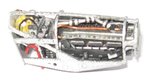
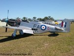
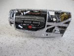
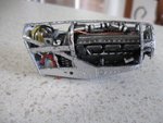
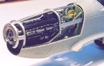
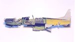
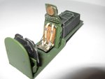
Hey guys as most of you all ready know i have started work on a Dragon 1/32 scale mustang nicked named the snifter. Over the next couple of mounths ill be posting the build up here. Being a GA classed pilot i have had the pleasure of flying this nice war bird as i use to be a admin for the museum wich stores the mustang in QLD. I have allready finnished most of the motor and detailed it. (seen in the pic below)

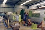
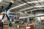
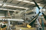
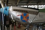
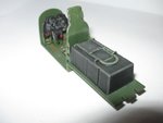
But im not pleased with the result its missing something to make it stand out. So i decided to take photos of the real thing inside and out!. I wish to make this model look as real as posible but still maintaining that used ww2 look ( I have a keen eye for detail). So i decided to add all the wires and frame work. If anyone has blue prints of the motor bay can you please send them on to me :).
 

Attachments

  • Img_0132.jpg
    Img_0132.jpg
    43.5 KB · Views: 145
These photos are of the rebuild. Wich i will use to help me throught the build of the kit.
 

Attachments

  • ME_2A68_110.jpg
    ME_2A68_110.jpg
    49.9 KB · Views: 152
  • ME_2A68_110a.jpg
    ME_2A68_110a.jpg
    53.8 KB · Views: 187
  • ME_2A68_110b.jpg
    ME_2A68_110b.jpg
    50.8 KB · Views: 142
  • GH_2A68_769.jpg
    GH_2A68_769.jpg
    42.9 KB · Views: 153
  • work%20008.JPG
    work%20008.JPG
    71.6 KB · Views: 155
LoL i did it again can a mod resize my photos i cant change them in edit. i did crop 800 by 600 and they are still to big.:(
 
So apart from the standed plastic parts i have added raditor hoses and fuel injection hoses to give the motor a bit more realisim but i wish to put more cables in. ill come back to the motor later on. Ill move on to the next step wich is the gauges.
 

Attachments

  • IMG_0150.JPG
    IMG_0150.JPG
    42 KB · Views: 125
With the gauges i used the back plate and the metal etch face plate as well as the plastic face plate. Covered the gauges so not to get paint on them then painted the lot flat plack. After all was dry i used silver and lightly dry brushed to give a used look. Then removed the masks of the gauges this is the end result. (And guys i found out my camera is taking huge photos its stuffed got i new one and ho my good better photo quality.)
 

Attachments

  • IMG_0155.JPG
    IMG_0155.JPG
    55.5 KB · Views: 135
  • IMG_0153.JPG
    IMG_0153.JPG
    51.9 KB · Views: 138
  • IMG_0154.JPG
    IMG_0154.JPG
    57.4 KB · Views: 129
Darn, can't seem to open the pictures ! Shame, as it sounds good so far. If you need any help with the cockpit fitting, let me know, as I've got pics I did for a magazine article. The main internal parts do NOT fit, and will need some 'assistance' in the form of shelves and spacers etc. Best to know now, before you spend ages detailing, then find the whole lot won't mate up!
Terry.
EDIT:- Came back for another look - the pics opened this time. Nice work.
 
thanks Terry i wouldnt mind the photos. I have just about finnished the cockpit ill post photos tommorrow with more steps taken to get their.
 
OK mate, I'll dig them out. They were taken on a 35mm camera - didn't have my digital one then - so I'll scan and post them asap. I'll also check my notes from the time, as I had huge problems getting anything in the nose area to align. I ended up binning the cowling supports, and gluing the cowlings in place, after a little surgery. Also, the prop had to be fitted with the help of plastic 'flanges', into the cowling, due to the alignment problems. This meant I couldn't display the engine on one side, as intended. The engine bay bulkhead didn't meet the fuselage sides, and needed a lot of work to rectify, same with the cockpit bulkheads and instrument panel! So, you might find a lot of work ahead of you, unless Dragon have rectified the fit problems, as mine was from the first production run, two years ago.
Don't be put off though as, with a bit of work and a lot of patience, it turns out nice in the end.
I'll get the pics up in a few hours time.
Cheers,
Terry.
 
Right mate! Found the 'reject' pics - the others were never returned by the magazine, and of course I don't have time to get re-prints of the decent ones. However, these should hopefully be good enough to show the problem areas.
PICS 1 2 show the pieces of plastic card, attached to the mounting points, in both fuselage halves (port only shown). These acted as shelves, onto which the cockpit floor was fixed, to allow equal spacing between each side, centralising the whole assembly. If you glue to one side only, the opposite side will NOT join-up, leaving a large gap. Note these were painted Interior Green, so that they wouldn't show after the floor etc was fitted.
PIC 3 shows all the internals in place, after aligning centrally. Note the seat has been moved back a couple of mils, as it was too far forward if the locating slot was used. There are also some additions, in the form of framework, fuel filler tube etc.
PIC 4 shows the gap around the front bulkhead, and the misalignment of the engine assembly and cowling support frame. The whole lot was manouvered to get the best fit, damaging some of the detail and paintwork on the engine etc in the process. It was later found that the cowlings, all of them, would not fit with the support in place, and this had to be removed, the cowlings trimmed here and there (trial error) and test fitted numerous times to get a decent fit. If you intend to leave off the cowlings, this area shouldn't be a major problem, apart from alignment for the prop. (See below.)
PIC 5 shows the plastic card 'flanges' I had to insert inside the spinner, in order to make the prop fit. As the prop shaft would no longer line-up with the engine, these were fitted, and slotted into the cowling, once the latter was firmly glued in place, otherwise, the whole prop would have been off to one side by about 3mm or more - very noticeable!
PIC 6 The rudder. The hinge at the top has a very noticeable gap, which needed filling and re-profiling, and the bottom hinge should be flush. The pics show the 'before' and 'in progress' stages.
PIC 7 Wheel bay/ gun bay. Not very clear in this pic, but the top of the wheel bay, just visible top left, was a poor fit, and would not bed down, even after trimming and sanding. I seem to remember I removed it after this shot was taken, did some more surgery, then refitted it. Note, on my example, there were some huge ejector pins on the top of this part, which at first looked like part of the kit; supports or similar. These had to be carefully removed.
If you are displaying the gun-bays open, then the gun barrels need to be cut, in front of the front wall of the bay, so that they align with the leading edge gun tubes. Then, the guns need to be moved back, otherwise the ammo feed chutes will not line up. You might want to add plastic card walls, and blank over the front wall as in the pic, otherwise there will be fairly large, and visble, open gaps. (Note that the upper feedway door, moulded as part of the wing-top, is easily cut out, but there is no internal detail; this will need to be scratch-built.) Note also the pieces of card covering the holes for the HVAR stub-mounts, which I didn't use. The holes were filled from the outside, then sanded smooth.
There were a number of other minor areas, which you will no doubt discover, but two that I recall were the fit of the tyres, needing a bead of superglue to seal the small gap between the rim, and a prominent mould-mark down the centre of the canopy, which will need fine sanding and polishing.
I hope this helps a bit,
Terry.
 

Attachments

  • Dragon P51 003.jpg
    Dragon P51 003.jpg
    39.1 KB · Views: 129
  • Dragon P51 009.jpg
    Dragon P51 009.jpg
    55.1 KB · Views: 137
  • Dragon P51 002.jpg
    Dragon P51 002.jpg
    20.4 KB · Views: 130
  • Dragon P51 001.jpg
    Dragon P51 001.jpg
    28.7 KB · Views: 134
  • Dragon P51.jpg
    Dragon P51.jpg
    38.3 KB · Views: 145
  • Dragon P51 005.jpg
    Dragon P51 005.jpg
    31.3 KB · Views: 130
  • Dragon P51 006.jpg
    Dragon P51 006.jpg
    47 KB · Views: 136
Thanks heaps for your information Terry ill put it to good use. Didnt realize the amount of trouble needed to fit the parts together:shock: . I couldnt sleep last night so i finnished the main part of the cockpit off.
 
After a few coffie's i gluded the deck and painted where the feet would wear and tear the wood floor by painting them with desert yellow.(first pic's) Once dry i dry brush linoleum deck brown over the top just lightly so to give a wood look. After all this i used vanish to finnish it off.
 

Attachments

  • IMG_0158.JPG
    IMG_0158.JPG
    86.7 KB · Views: 117
  • IMG_0159.JPG
    IMG_0159.JPG
    76.6 KB · Views: 130
The cockpit in the real mustang is finnished of in british racing green dont ask me why but thats what they used. Knowing this i decided to paint cockpit in flat dark green mix. With the air brush i sprayed the platfrom. Here is the tricky part with a cotton wool bud i dipped in acrylic thinner rub the area back and forth where the feet rest making the wood grain show through. To finnish it of i dusted the feet rest with tamiya weather master set A. Moving on to the seat like allways i had to modify it by adding two strips of plastic with three holes to give it a more realistic look. I find the best way to paint seats with metal etch seat belts is to paint the seat first then glue the belts in place. To simulate leather on the seat again used desert yellow over the top use linoleum deck brown again but this time thin it with water i used one part paint to three parts water. After i painted the seat belts then went over the lot with a sepia wash and a dry brush of silver.
 

Attachments

  • IMG_0160.JPG
    IMG_0160.JPG
    24.7 KB · Views: 115
  • IMG_0163.JPG
    IMG_0163.JPG
    34.8 KB · Views: 123
  • IMG_0157.JPG
    IMG_0157.JPG
    85.5 KB · Views: 125
  • IMG_0162.JPG
    IMG_0162.JPG
    29.2 KB · Views: 119
Looking good so far. Just one point concerning the seat though. Although the kit part is moulded as if it has a back cushion, which you've painted accordingly, the wartime P51D seat back was slightly dished, to accommodate the back-pack parachute, with the seat pan being similar, to accept the dinghy pack. That said, I realise you are building a replica of the rebuilt Mustang, so no problem! Great work, looking forward to the next bit.
 
Looking very nice and interesting Greedy.Good work.
As far as the resizing is concerned, please find and download program called Irfanview.It is both a free software and very usefull one.Resizing with the application is a piece of cake.Please use this before you are going to upload your pics here on the forum.
 
Thanks for the name of the program when i get back to qld ill download it and use that program. I have done alot more to the plane but ill post the rest later once i get home.
 

Users who are viewing this thread

Back