P51-D "Snifter" (1 Viewer)

Ad: This forum contains affiliate links to products on Amazon and eBay. More information in Terms and rules

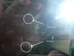
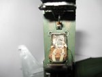
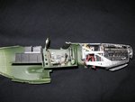
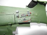
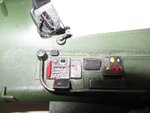
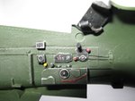
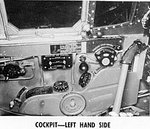
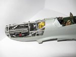
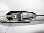
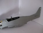
Hey guys im back, Ive made alittle more progress. I have finnished the main deck of the cockpit of by adding two gauges in the floor for both left and right fuel tanks. And finnished of the battery behind the seat. I also did the side panels.
 

Attachments

  • cockpitfuel.jpg
    cockpitfuel.jpg
    26.8 KB · Views: 76
  • IMG_0166.JPG
    IMG_0166.JPG
    32.4 KB · Views: 58
  • IMG_0164.JPG
    IMG_0164.JPG
    51.8 KB · Views: 88
  • IMG_0165.JPG
    IMG_0165.JPG
    45.9 KB · Views: 86
So far this model has come along real good but the cockpit on the other hand looks like a nice fit but its far from it! What Air frames has is right the main deck does not line up on both sides its about 2 mm out each side. other then that its been a great fit!.
 
Good job so far. I hope you can line-up the engine OK - you might have to move it around a bit. I left mine un-glued until I got it as close as possible to central, but even then it was still 'out'.
 
The engine seems to be a good fit. Last night i was looking at real cockpits of the mustang and noticed the pilot lights (map lights) had a curly wire hanging out the back. So i added that to my model using a piece of wire and a needle i wrapped the wire around it. Then with a micro drill drilled two holes one in the back of the light the next in the wall off the feasluge glude and streched into place the wire. (As seen in the pics below)
 

Attachments

  • IMG_0167.JPG
    IMG_0167.JPG
    45.5 KB · Views: 59
  • IMG_0170.JPG
    IMG_0170.JPG
    50.4 KB · Views: 85
My main aim today is to have the cockpit in and motor all together!. I have a question for all you plane buffs what color should the radiator be?
 
Greedy - you are doing a great job of displaying weathering typr wear on the instrument panels, etc - but in real life they didn't take much abuse

I attached some pics of the P-51B but not much changed on the D
 

Attachments

  • P51BRtCockpit72.jpg
    P51BRtCockpit72.jpg
    47.2 KB · Views: 81
  • InstPanelLeft72.jpg
    InstPanelLeft72.jpg
    54.9 KB · Views: 86
  • P51BLhCockpit72.jpg
    P51BLhCockpit72.jpg
    50 KB · Views: 55
That might be the case for a american mustang. As for the Australian mustang ( Snifter ) i was able to get photos before the resteration and from them their is alot of warn parts inside wether this is due to old age or not i dont know?. But i guess since i used the photos alot for the painting of this model im to far head to change now. The model after finnished will be presented to the syndicate ( joint owners of most of the museums flying stock ) at the next brisbane model show. Then mostlikely placed in the Canberra museum.
 
Yay i finnished the fuselage off and it looks great!
 

Attachments

  • IMG_0171.JPG
    IMG_0171.JPG
    38.7 KB · Views: 62
  • IMG_0173.JPG
    IMG_0173.JPG
    35.6 KB · Views: 57
  • IMG_0174.JPG
    IMG_0174.JPG
    28.9 KB · Views: 56
No i ran out of green paint! Wheel time to do the landing gear. These are great! spring loaded landing gear but there is one problem the keep binding up so im going to have to think about how to make them better and stronger! ill post pics soon.
 
Great work mate! It's best to leave out those 'gimmicky' springs on the landing gear - even if they do fit properly, the tension means that the model will sit too high on it's legs, as the gear will not reproduce the look of 'under load'. On mine, I calculated where the oleos would be in relation to the the gear legs, when 'on the ground', and cemented them accordingly.
 
I have fixed and finnished the struts on the landing gear. First it was brought to my attention that the ride hight of the model is to high. So i went for a drive to the real snifter and checked out the landing gear plus did some measurements. After a short trip i brought evergreen scale model strips .080" rod to replace the landing gear shaft. I cut the shaft off then used a 2mm drill and then cut and glued the shaft into place. The main cylinder was bored out using 2.5 mm drill bit. So the shaft would slide, to hold everything in place i used a micro drill to slot the shaft. Once all back together i used a pin to keep it all in place. I should note that i thought out the old springs and used ones from old pens streched and cut to size. Now the ride hight is spot on.
 

Attachments

  • IMG_0182.JPG
    IMG_0182.JPG
    92.1 KB · Views: 59
  • IMG_0184.JPG
    IMG_0184.JPG
    52.4 KB · Views: 56

Users who are viewing this thread

Back