RCAF Starfighter, 1/48th scale - Part Two

Ad: This forum contains affiliate links to products on Amazon and eBay. More information in Terms and rules

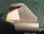
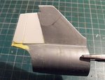
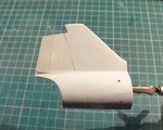
Thanks Cory. I'm hoping to get the other side, and the top of the fin done tonight. Pics soon.
 
Thanks Hugh.
The starboard side of the jet-pipe opening has now been treated to some 'Milliput', and will be sanded in unison with the port side once fully set.
A strip of plastic was 'superglued to the top of the fin, trimmed to the rough shape, and then lightly sanded, in order to raise the height of the fin. The 'stabilator' is just loosely fitted to provide an 'aiming point' for the depth required. Once the 'Milliput' areas have been sanded to the final shape, the whole assembly will be polished to remove sanding marks, and then primed, to check for any defects, and corrected as required.
Incidentally, what look like huge, raised rivets and panel lines are actually 'ghost' images within the plastic, as they've all been removed with the miniature chisel, and then sanded.
Given I have the time, I'll get back to work on the RCAF bird tomorrow, after completing the above work on the Danish version.
Thanks again for your continued interest, and I'll post more soon.
 

Attachments

  • DSCF0001 (6).JPG
    DSCF0001 (6).JPG
    78.8 KB · Views: 50
  • DSCF0003 (5).JPG
    DSCF0003 (5).JPG
    80.4 KB · Views: 44
  • DSCF0001 (7).JPG
    DSCF0001 (7).JPG
    80.6 KB · Views: 42
Yeah, working on me back, hanging from the ceiling, was bl**dy tiring, I can tell you !
Thanks chaps. Those oxygen hoses arrived today - but the 'Postie' p*ssed off before I could get to the door, so I'll have to collect them from the sorting office on Monday.
Hopefully, I'll get the final sanding and polishing done on the tail unit today, then get back to the RCAF bird.
 
The sanding to shape has been completed, and a rough couple of coats of primer brushed on to the tail unit. This has revealed a couple of small areas, on the starboard side, which will need further attention - the base of the rudder being the most important, plus cleaning out the rudder hinge line, which can be done as the primer is sanded back.
The vertical joint between the extension and existing fin should smooth out, and is of little concern, as there is a panel joint here on the real aircraft. Also, once a coat of primer has been sprayed on the entire airframe, and a couple of coats of the dark green applied, such minor blemishes should, I hope, become virtually invisible.
The two 'holes' have been countersunk (on both sides of the tail unit) for the navigation/formation lights, and will be painted and glazed towards the end of the build.
 

Attachments

  • DSCF0002 (6).JPG
    DSCF0002 (6).JPG
    78 KB · Views: 56
Thanks Andy and Evan.
I'm a bit annoyed at the 'Postie' (presumably not the usual bloke who delivers), as I wanted to get on with the ejection seat for the RCAF bird, but can't go further until I see the oxygen hoses, and work out what's needed.
 
I think all postmen get more and more lazy. Also here in Poland. I haven't mentioned it to you Pal but I had to go to the Post Offce here and picked up the recent package there. No problem for me but I have asked what the reason for a such procedure was. And I got a reply that a such small boxes aren't deliverd by a courier. I thought , interesting. There wasn't a such service years ago and similar packages were bringing by a postman to homes without any problem. All goes to the dogs.
 
Here it seems to depend on the person delivering your mail. The woman who's been doing it recently has been great, and has been dropping off packages at the door, instead of how they normally do it by putting a notice in your mailbox if it's too large to fit. We have these community mailboxes at the end of the street which have small containers for each house, and then two larger ones that they'll put your package in, and they put the key for the box in your small house box. Works pretty well, but it's been nice lately not having to go to the post office to pick up larger ones.
 
My regular Postman is great. He'll wait - even stepping back to look up to the upstairs windows, in case I'm still in bed. If no answer, he automatically leaves parcels, or packages too big for the mail slot, at the shop next door.
Some time ago, I arranged for this to happen 'officially', by filling-in a form at the Sorting Office, but the only time it happens is with my regular Post guy, who does it off his own initiative.
 
Thanks Hugh.

The RCAF bird is still progressing, but as much of the work done so far has been measuring, cutting and drilling plastic strip, in preparation for modifications to the seat, there's not much worthwhile to show.
Therefore, I've done a bit more to the Danish version which, although it doesn't look much, took a heck of a long time, due to the method of assembly designed by ESCI back in the mid 1970's. Instead of fitting all cockpit components to the cockpit tub, the instrument panel and shroud are assembled separately, and fitted to one side of the fuselage, followed by the tub and rear bulkhead. Sounds simple enough, but took ages ensuring everything would be properly aligned once the fuselage halves were joined.
Anyway, here's how it looks to date, and bear in mind this is more or less an 'OOB' build, apart from the mods to the tail. As the canopy will be closed (being a one-piece moulding), the cockpit detail will be restricted to the throttle handle (power lever), made from plastic rod, the drilled-out gun sight lens, and some extra detail on the Martin Baker seat, taken from the Revell kit, which was fitted in place of the C2 seat in RDAF service.

PICS 1 and 2. The cockpit painted and installed, with the instrument panel using 40 year old decals from the ESCI kit, and the radar panel decal from the Revell kit. The power lever was made from plastic rod, painted and with 'buttons' from dots of paint, then cemented into a hole drilled in the quadrant, and a line cut for the lever slot. Not visible here is the gun sight head, which has been countersunk and will be painted and glazed later, before fitting the sight screen.
PIC 3. Not taking any chances, even though the landing gear geometry suggests it won't be a 'tail sitter', so a couple of chunks of roofing lead have been installed over the nose wheel bay, held in place by 'Plasticine'. Hmm, I hope the church roof doesn't leak too much now .....
PIC 4. Fuselage joined, and will have the joints and seams sanded once set.

Next step is to modify and enhance the kit's jet exhaust and fit it into the tail section, before fitting this to the fuselage and continuing with the main construction.
Many thanks again for your continued interest and compliments, and I'll post more soon.
 

Attachments

  • DSCF0006.JPG
    DSCF0006.JPG
    70.2 KB · Views: 68
  • DSCF0007.JPG
    DSCF0007.JPG
    55.6 KB · Views: 59
  • DSCF0008.JPG
    DSCF0008.JPG
    45 KB · Views: 52
  • DSCF0009 (2).JPG
    DSCF0009 (2).JPG
    41.2 KB · Views: 49

Users who are viewing this thread

Back