**** DONE: 1/48 Kittyhawk IV "Cleopatra III" - Aircraft in Foreign Service WWII

Ad: This forum contains affiliate links to products on Amazon and eBay. More information in Terms and rules

For what it is worth, the Red Roo decal sheet has colour elevations of all surfaces. They show no variation in the "dark Olive Drab" surface colour other than the circle under the insignia and code.

Thanks for that sir!

NEW INFORMATION..............

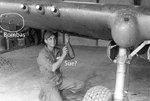
The wire in front of the tail wheel is the Static Ground.......... from Pilots Manual!
The LUMP I point to in my post 143 in front of the static ground, is the Hydraulic Vent............ from pilots manual.
The wire on top is still unknown.

So perhaps the triling wire you are pointing out is a static ground wire, just farther forward?

Good stuff Bill. I don't think it's the static wire because the one in front of the tail wheel is also there as Wojtek pints out.
 
Last edited:
In some shots, it looks rather flexible, quite like a trailing aerial wire. Did some P-40s use a trailing aerial, for longer-range comms?
If so, then some sort of crank handle will probably be visible in the cockpit, at a guess, on the starboard side. Just a thought.
 
My guess is that line coming from the underside is some sort of fuel vent or overflow. I have a picture somewhere of the underside of the fuselage/wing with that housing removed and I remember there being some tubing there. It could be an extension of that. I'll have a look when I get home tonight.
 
Cheers Glenn. I've been flipping through several manuals and have also thought that it may be associated with the fuel vent as diagrams show the vents to lead to this location.

P-40 Fuel System.jpg
 
I'm thinking no. The line in the photos seems to come out of the back of the bulge but the fuel vents are just in front of the end of the bulge.
 
Might have been a piece of hose added by a mechanic that was tired of cleaning fuel spill off the underside of the fuselage. In any case I don't think it was original equipment on any P-40. Sorry Andy but I completely forgot to look for that picture when I got home last night. Will look tonight.
 
Last edited:
Sorry Andy, I could not find the picture I was thinking, but did find these from Bert Kinzey's P-40 In Detail Part 2. they show the forward half of the underside of the wing with the housing removed. You can see the plumbing going aft along the center joint of the wings. Hope it's of some help.
 

Attachments

  • P-40 underside plumbing 1.jpg
    P-40 underside plumbing 1.jpg
    132.3 KB · Views: 137
  • P-40 underside plumbing 2.jpg
    P-40 underside plumbing 2.jpg
    133.1 KB · Views: 111
Sorry Guys, but if I catch you properly you are looking at the incorrect area. I'm afraid. I"m about to agree with Andy that it is a part of the fuel system. Im my humble opinion it may be the part of the vent marked with the numbers 8,7,6,5,4.

P-40 Fuel System_.jpg
 
Wojtek, I think you have it! Thanks for your help in sorting this out. I can't believe I missed that!

On another note, in my ongoing research, I came across this detail for the wing bomb rack. Not great but it supports what's been said already. P-40 fans might like this site where I found lots of great references including some fabrication drawings: P-40 Parts part 1 by Dan Collier.

P40  Bomb Rack Detail.jpg


Heading down to Nanton today to work on the Mossie. All I've been doing is some boring sanding and scribing so nothing exciting to show.
 
50 pond bombas eh? Interesting. Don't see any evidence on Waters' plane.
 

Attachments

  • GB20-1d P-40-18.jpg
    GB20-1d P-40-18.jpg
    77.5 KB · Views: 98
Last edited:
Andy

The top whip aerial is part of the IFF system fit. I"m not sure of the exact system fitted to this aircraft, but the official mod list includes SCR-535a or SCR-695 for later marks.

250064.jpg


Cheers

Peter
 
Last edited:
Thanks Dale and Peter. Peter, according to the maintenance manual, radio equipment in this production block would be "SCR-274-N and SCR-695, or SCR-522 and SCR-695 with provision in both cases for the SCR-515 radio in both cases." Unfortunately, every reference I've been able to find on line for these pieces of equipment doesn't talk about the related antennae.

Anyway, moving along, I present the gunsight which is basically the kit part with the reflector glass lopped off and replaced with a thinner piece of clear plastic.

13122101.jpg


The fuselage/wing joint was filled with sprue, sanded down, rescribed, and then rivets were added with a small twist drill.

13122102.jpg


The kit does not supply the diamond pattern tire that is evident on this aircraft so I decided to cut the pattern myself. I saw this nifty jig on another website that I quickly fabricated from card and used to ensure the pattern was cut at the same angel every time.

13122103.jpg


What I didn't realize is that I actually need two jigs, a left and a right, as no matter how you turn the tire you can't cut the opposing pattern in the same jig. So for that, I used my Mk. 1 Eyeball rather than make another jig. The problem now is that I made the pattern too big so I think I'll go back over it again and make more cuts half way between the ones I already did.
 

Users who are viewing this thread

Back