**** DONE: Revell P-61A 1/48 scale, Nocturnal Nemesis, Night Fighter GB.

Ad: This forum contains affiliate links to products on Amazon and eBay. More information in Terms and rules

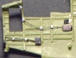
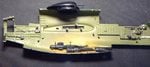
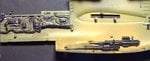
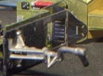
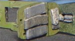
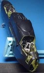
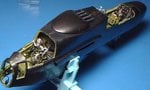
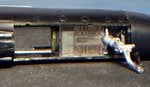
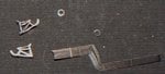
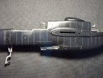
Thanks guys. Well I'm up now so on to work. I want to get the halves together today so I better get cracking. Starting out with a little research first. There appears to be a swinging armor plate that sits just before the gunner in some of the planes and I've seen one modeller add it in. I'm checking at the moment to see if this plane had it or not... Hmmm... I'm looking at the moment and the answer is no. Nocturnal Nemesis did not have those swinging plates although I have found a nice picture of the gunner opperating the turret. :) Well that's one less thing to worry about. Just one more item I need to add in a couple of places before I add the cannons... the relief tubes. I'll be back before long. :)
 
Thanks, I think I finally found a good focal point. Of course it will have to change as the plane gets bigger... but not yet. :)

I finished painting the back left side and have gone on to the closeing of the halves. I've had to go over a few different resources before continueing. Then I made and attached the forward landing gear assembly... Ok, I started the closing by making sure I had added more weight in key locations. I found a nice pocket just below the gunner's station and added weight there. Then I did a dry fit to see if anything was interfering with anything else. Found a peg pushing into one of the weights so I clipped it. After that, the fit was just fine for the left side. Dry fitted the right side and found some material pushing against one of the photo etched parts. Removed a little of the offending material and the fit was perfect. Then I added the guns and the gun bay covers. Since the gun bay will be closed, I glued them all shut.

Next, I started on the external photo etched parts pack. Looking down the ladder shaft there was a photo etched side panel fore and aft. I took photos in hopes you can see both. Mostly the large one stands out in the aft part. The small one in the front part is visible in a couple of shots. Once the photo etched stuff was on, I started glueing the sides together, left side first. After it dried suffiently, the turret was fitted in. I'm going to have to post the next five pix in the next post.
 

Attachments

  • closing 003.jpg
    closing 003.jpg
    28.4 KB · Views: 133
  • closing 004.jpg
    closing 004.jpg
    24 KB · Views: 130
  • closing 005.jpg
    closing 005.jpg
    12.2 KB · Views: 125
  • closing 006.jpg
    closing 006.jpg
    28.7 KB · Views: 125
  • closing 007.jpg
    closing 007.jpg
    22.6 KB · Views: 136
Here are the last of my pictures for today. The final fit of the two halves was good. Took my time letting each dry before adding the other. Did a dry fit of the part between the nose cone and the forward end of the fuselage. This would be the part where the radar assembly would sit if the nose cone was off. Found a couple protrusions that I had to sand off so the cone would fit properly. Then I glued the cone on once I was sure of a good fit. I'll tell you. I could feel those weights I added. :) This pup is not going to be a tail sitter. The final photos show the sides together. Took a while just admiring it. I have never in my life put this much detail in any model I've built, especially having it turn out this well with my feeble skills. :) I have to thank all of you guys for showing me how and for the encouragement. :)

By the way, I know that some of you know more about this plane than I do. Please feel free to point out anything I missed or still need to do.
 

Attachments

  • closing 008.jpg
    closing 008.jpg
    27 KB · Views: 134
  • closing 009.jpg
    closing 009.jpg
    34 KB · Views: 116
  • closing 010.jpg
    closing 010.jpg
    17.4 KB · Views: 116
  • closing 011.jpg
    closing 011.jpg
    34.9 KB · Views: 126
  • closing 012.jpg
    closing 012.jpg
    31.2 KB · Views: 117
Thanks Vic. I'm trying hard to work with the pictures. This next batch isn't really good but I was able to tone done the glare. Since I've worked with this model before, I'm very much aware that the fit of the windows leaves a lot to be desired. Fortunately, I've come up with a poor man's fit. I say poor man's fit because I don't feel like paying $30 just for a couple of stupid windows that may or may not work. Anyhow, I used 0.020" sheet styrene and cut it to the same width as the side of the model. Photo's say it all. The starboard side by the gunner gets two layers. I did a dry fit afterward and the windows fit nicely. :)
 

Attachments

  • windows 001.jpg
    windows 001.jpg
    67 KB · Views: 134
  • windows 002.jpg
    windows 002.jpg
    16.1 KB · Views: 137
  • windows 003.jpg
    windows 003.jpg
    25.4 KB · Views: 138
  • windows.jpg
    windows.jpg
    47.6 KB · Views: 140
I had run these photos using MS Photo Editor... The program on my laptop... and it not only lets me tone down the glare but it also decreases the memory size of my photos allowing me to post them a bit faster. :) So it looks like I'll be using two computers for my pictures for a while.
 
Really nice work Bill, it's turning out very well indeed. The only thing I would have done different, if it's possible to do so, would be to add the turret and nose gear later, which will allow sanding/filling of the fuselage joint to be undertaken without fear of damage to those two components, and also make masking and painting easier.
 
I would have if I could have. The turret has an interlocking bezzel that can only be put on when the halves come together according to the directions. The forward landing gear also has to be included when the sides come together otherwise it will not fit into place. It's part of the model's design and I agree it's not a very good design but it is what it is. :( As it is now, both turret and forward landing gear are moveable and fortunately I have a little experience working around these two items. :) I'm more worried about the gun grips on the two seats.
 
Thought that might be the case. It's a pain when the design is like that, as I'm always bothered that something will go 'ping' when handling !
 
Added a few photo etched parts in the ladder well and forward landing gear area. I was kind of surprised with this detail. It gives me a greater sense of what it looks like around this area. Spent the remainder of today putting in rivet lines and taking out seams. Will post more pix in the morning. :)
 

Attachments

  • Photoetch.jpg
    Photoetch.jpg
    45.5 KB · Views: 123
  • underside1.jpg
    underside1.jpg
    94.2 KB · Views: 129
  • underside2.jpg
    underside2.jpg
    79.7 KB · Views: 130
  • PE2.jpg
    PE2.jpg
    60.4 KB · Views: 124
I guess I'll show at least the verticle lines before I retire for the evening. I'll finish the horizontal lines tomorrow along with getting rid of the seams. :)
 

Attachments

  • windows 004.jpg
    windows 004.jpg
    36.3 KB · Views: 142

Users who are viewing this thread

Back