Navigation
Install the app
How to install the app on iOS
Follow along with the video below to see how to install our site as a web app on your home screen.
Note: This feature may not be available in some browsers.
More options
You are using an out of date browser. It may not display this or other websites correctly.
You should upgrade or use an alternative browser.
You should upgrade or use an alternative browser.
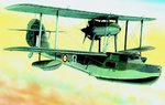
Revell 1/72nd Supermarine Walrus Mk.1
- Thread starter Matt308
- Start date
Ad: This forum contains affiliate links to products on Amazon and eBay. More information in Terms and rules
More options
Who Replied?- Thread starter
- #22
Matt308
Glock Perfection
Alright...
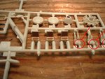
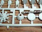
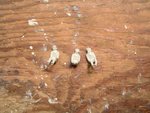
Next are the seats, metal with leather pads. I will clean up the lower pads with a touch up of steel. Won't see much of them anyway with the figures seated. Speaking of figures...
The men are on the right. Note the common moldings for the figures. Well, Dr. Mengele here, has a little suprise for these British flyboys to make them a bit more "interesting".
Attachments
Airframes
Benevolens Magister
Good work Matt. BTW, I like the idea of your paint stand, with the 'slots' for paint bottles etc., in one of the pics. Is it something you made?
- Thread starter
- #24
Matt308
Glock Perfection
Now to focus upon beginning the engine housing.
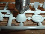
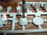
A hole was not provided for the front of the engine housing. The oil cooler inlet was blocked! Why I have no idea. So out comes the countersink, followed up by a properly sized drill bit twisted by hand to complete the hole.
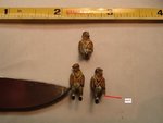
Dr. Megele begins his work. Sorry chaps, but off with your heads. Mengele will remove their heads and reattach them in a more interesting position. Pilot looking port. Copilot/Observer looking down and starboard. Rear gunner/observer looking starboard (remember he faces aft) and high.
Unfortunately my fat fingers broke off one bloke's leg and I lost it.
A hole was not provided for the front of the engine housing. The oil cooler inlet was blocked! Why I have no idea. So out comes the countersink, followed up by a properly sized drill bit twisted by hand to complete the hole.
Dr. Megele begins his work. Sorry chaps, but off with your heads. Mengele will remove their heads and reattach them in a more interesting position. Pilot looking port. Copilot/Observer looking down and starboard. Rear gunner/observer looking starboard (remember he faces aft) and high.
Unfortunately my fat fingers broke off one bloke's leg and I lost it.
Attachments
- Thread starter
- #25
Matt308
Glock Perfection
- Thread starter
- #26
Matt308
Glock Perfection
Airframes
Benevolens Magister
You can make the one-legged guy the observer, an eastern European volunteer, named Ivan Nokalegoff !
Catch22
Major
Looks good so far!
- Thread starter
- #30
Matt308
Glock Perfection
You can make the one-legged guy the observer, an eastern European volunteer, named Ivan Nokalegoff !
Good work Matt....sometimes there is collateral damage when modelling ..at least you didn't lose one of the heads!!
..at least you didn't lose one of the heads!!- Thread starter
- #32
Matt308
Glock Perfection
- Thread starter
- #34
Matt308
Glock Perfection
Good work Matt....sometimes there is collateral damage when modelling
Actually I did. How I found it on the garage floor is beyond me. Pure luck since it is the size of this "o".
- Thread starter
- #35
Matt308
Glock Perfection
I have built the match box one just recently, tried a couple different schemes, and finally went with an all grey one flying over the beaches during d-day complete with invasion stripes..just have to do the markings and some weathering
Bernhart, if I'm not mistaken, Revell and Monogram have merged and I think they are the same kit. Someone correct me if I'm wrong.
- Thread starter
- #36
Matt308
Glock Perfection
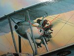
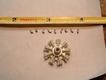
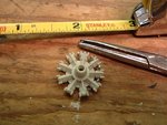
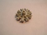
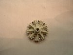
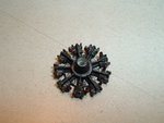
Engine first.
The rotary engine has small exhausts elbowing out of each cylinder head. A little improvisation with solder, the wrong kind of superglue (Loctite Gel) and much cussing you end up with decent looking exhausts.
And with those short straight exhausts right fore of Mr. Nokalegoff, not only is he missing a leg, he's missing any resemblence of normal hearing. Can you imagine looking through binoculars for 4 hours searching the bright sea and listening to 700hp screaming right behind you? Talk about fatiguing. Made me think about the intercom system on the Walrus (if there is one). Certainly they don't have headsets, as Mr. Nokalegoff would have had to turn his gain up to 11 to hear any intercom instructions. I suspect there was no intercom, which destroyed the role of the gunner having to coordinate turns with the pilot. Brave men indeed.
So some engine pics first.
Attachments
- Thread starter
- #37
Matt308
Glock Perfection
Wildcat
Major
Looking good Matt!
- Thread starter
- #39
Matt308
Glock Perfection
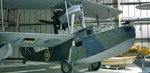
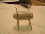
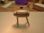
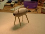
Next engine housing.
This proved to be a royal b!tch. After much dry fitting, cussing, dry fitting and more cussing, I couldn't figure out how the engine housing struts aligned. Only have doing some research did I finally conclude that the engine housing is assymetically mounted between the wings!
The engine housing is mounted yawed to the airplane centerline. Why? I can only guess that this is to counteract the effect of torque. If anyone knows, please post an explanation.
The engine housing must also be assembled with the struts attached. Thus the putty and sanding work was a little precarious with the support struts in the way.
More work is required for the aft engine housing vents. But that will have to come a bit later. I'm off the store to get some dinner for the family and grab me a beer.
Attachments
Catch22
Major
Liking the progress!
I assume you're doing it in Pacific Fleet markings and not European?
I assume you're doing it in Pacific Fleet markings and not European?
Users who are viewing this thread
Total: 1 (members: 0, guests: 1)