Lucky13
Forum Mascot
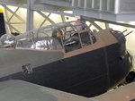
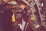
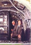
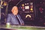
I've got an actual Lancaster, WWII survivor....
Looking forward to your next update!
You're going to have to elaborate on that a bit more, Jan - I'm intrigued.
Gerry
Everybody have their books, thought that I'd beat them with WWII survivor of the Lancaster....
") )
)