1:32 scale Lancaster Mk.1 Hachette Partworks

Ad: This forum contains affiliate links to products on Amazon and eBay. More information in Terms and rules

Well, I think I'm clearer on what Jan meant now. I misread his original post because of the comma. I had interpreted it as him having a surviving Lancaster. Now, I know that's highly unlikely unless Jan is keeping his Euromillions win to himself. Or maybe he had an original factory model of the Lanc? However, it's become clear that Jan knows a surviving Lancaster crew member. In that I think he is privileged, as there can't be too many aircrew left at this stage. My Dad had two cousins who served on Lancs during the war. Both were air gunners and both stayed on in the UK afterwards. Unfortunately, I never got to meet them while the were alive, something I regret now.

As I said previously, I have a few questions which I need answers to in order to progress. The first question relates to the flare chute/step which we've discussed previously. See photo below. As an early Lanc, S-Sugar probably had this still fitted and the kit supplies the parts, including the brass plates. My suspicion is that the brass plates are post-war commerative plaques on the BBMF Lancaster, otherwise I can't think what other function they might have. Can anyone clear that up?

Flarechute_zpsd235d200.jpg


My next question is about the colour of the interior handrails/safety rails etc. The instructions for the kit have these as yellow. In most of the colour photos of Lancs that are restored or awaiting restoration, they are in yellow also. You can see the yellow handrail to the bomb aimer's position in the next photo. and a yellow hand rail is visible in the flare chute photo above, of the BBMF Lanc. In fact it would make sense in a badly lit aircraft, at night, that a bright colour would be used for visibility. Then I found the second photo below, which is the cockpit of S-Sugar. Here the handrail is in black. Now I'm wondering if the yellow is another post-war refinement. in truth, they would probably stand out better in the model in yellow but I would rather go with what is accurate for the period.

Yellowrail_zps5e6bf2fa.jpg


S-Sugarcockpit_zpsfb1ee15c.jpg


My final query is about seatbelts. I've got good references for the pilot's and I've seen some refs for lap belts for the radio operator and navigator. How was the flight engineer secured? I've seen a diagram for the Eduard 1:48 Lancaster set which attaches the belts to the back of the folding seat itself. Is this accurate, as I've not seen any belts in photos of this seat? Again, I've seen some refs for the gunners' positions. But any refs for any of these would be a great help.

The build progresses slowly. I am installing tricky detail into the crew cabin and will post some shots in the next day or so. As a teaser, here's a shot of of the electrical distribution panel which is located opposite the radio operator's station. I thought I'd better show it separately as it gets quite lost in the black interior. It's a kit assembly with the decals sandwiched between the front and back metal sections. The switches (supplied) were added and the decals are from an Airscales 1:32 placard set. Eventually wires will be added to most of the side connectors but these are better left until the panel is installed, I think.

Lancelectricalpanel_zps3e4390fc.jpg


That's it for now. Hopefully, I'll get the photos of the installed panels out next post.

Gerry
 
Goods stuff Gerry.
That large, shiny brass plate in the BBMF Lanc is, I'm fairly sure, a dedication, although it, and the chute, were not fitted when I flew in her. I haven't seen such a plate in period shots of Lancs. However, the smaller, upper plate is, from memory, the safety instruction plate for the operation of the chute, and would be on the original.
It's possible that the later, port side, large chute was fitted at some stage, although I haven't seen any photos showing the exetrnal chute to support this, and this larger item was normally fitted when H2s occupied the floor space immediately aft of the bomb bay bulkhead and step, so I'd stick with the kit set-up.
Note that R5868, 'PO-S' underwent a deep service and upgrades, being returned to Avro after it's first tour with 83 Sqn as OL-Q, and a number of up-grades and changes were made. As a very early Lanc, she may well have had a green bomb aimer's compartment and cockpit, although photos show what appears to be a black BA area, and I've seen interior shots where the cockpit looks like the later black. However, that colour shot shows a green cockpit, with black nose compartment, and the black rails. This could all be, and probably is, due to the many changes, repairs and other mods made in her later life, when she was retired to a technical training school. And who knows what was done when she was eventually prepared for display in the RAFM !
What we see today is far removed from how she looked in service!
The yellow colour on rails, handles and hatch frames is a post war safety colour, but I've seen many wartime shots, and some film footage, showing yellow, and also cockpit grey- green rails, vertical radio supports and other handles etc. - a logical choice to aid visibility and location in the dark, and possibly a Group, Squadron, or individual crew choice. I think I'd paint the kit parts yellow, or green, as I believe any of the three colours could be correct.
As for the Flight Engineer's lap belt, from what I've seen, and what I remember from those Lancs I've been in, this was attached to the folding frame of the seat, although whether it was ever used is questionable, as the FE often stood up a lot of the time, using the seat for longer legs of a trip, and I've heard, and read, a number of accounts of the FE floating around the cockpit, having to hang on to whatever he could, when the aircraft was thrown into a 'corkscrew' or other evasive moves.
Hope this helps, and looking forward to the next bit!
 
Great stuff Gerry.


I didn't realise you were going down to electrical distribution panel level!

I have a pair of the bomb selector panels if you would like me to post pictures? They are about 8-9" across and 4" tall.
 
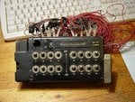
Like this? This is the bomb station selector, with the jettison bar to the right. This unit was mounted at the bottom left of the bomb aimer's main armaments panel, on the front stabroard side of the compartment.
 

Attachments

  • Bomb panel 002.jpg
    Bomb panel 002.jpg
    127.4 KB · Views: 145
Found that, along with some other bits and pieces, under a huge model railway layout in the attic when helping to clear the house after the sudden death of my ex-mother in law's friend. Apparently it was earmarked for use as a controller of some sort, on the model railway! BTW, the sudden death was a result of apparently slipping on scree in the Lake District and going over the edge of a cliff, whilst watching a Tornado flash past in the valley below!

Gerry, I've just had a closer look at that photo of 'Sugar' in the RAFM - the hand rail actually appears to be cockpit grey green, the colour looking darker due to shadow. This would fit with the original cockpit colour, as the black was a later introduction on the production line, after suggestions from 'the field', where units painted this area black themselves. So this bears out the choice of black (probably just over-painted when the cockpit and nose were done locally), green for original, early Lancs, green left when black re-painted locally, or yellow - possibly a factory colour and/or a 'local' addition.
 
Terry,

Yep..that's one..the main panel and along with it goes 50/659 which is almost identical but does not have the indicator window or lamp (BTW, the missing item where the hole is on yours is a light and a neat little rotating cover...also missing is the knurled silver thumb wheel on the to right side that rotates a legend "Container", "Distributor" , "Single and Salvo" and "Safe except for jetison" in the rectangular window.)


D


PS..thanks for the tip on the Type 35!!!
 
Last edited:
Yes Darryl, it's a shame about the missing bits. These, and the rest of the complete control panel, had already been thrown in the skip, by the ex-MIL, before I got there!
Stupid woman ............
 
Thanks Guys. There's an awful lot there to digest since my last post. Firstly, Terry and George thank you both for the information answering my questions. I should really have looked in on Bill's Lancaster build again, as Terry had already answered some of my questions there. The information regarding the flare chute and seat belts confirmed my suspicions but it's great to have a second opinion - and such an immediate response at that.

I suppose it's fair to say that I'm not hoping to replicate exactly S-Sugar's interior. That would be almost impossible at this stage and it may not even end as S-Sugar on the exterior. What I am attempting is a reasonable resemblance to a generic Lancaster Mk.1 or III of that period. So, within that brief, keep an eye on what I'm doing and shout if you see anything that's shouldn't be there.

Darryl and Terry, some of the panels for the bomb aimer's compartment are supplied. I haven't come to that part yet to look at them in detail but certainly that reference will be handy for detailing - or scratch-building. Terry, that's an awful story about your mother-in-law's friend. What an unforseen way to go. And Evan, Wayne and David, thanks for looking in.

Well, I promised some shots of the start of the cabin equipment being fitted and here they are, at last.

Fullcabinsb_zpse18ffd9c.jpg


Photo 1. I gave the cabin a coat of black and then distressed it to get that 'lived in' feeling. This was mainly achieved by gentle sanding with fine wet dry paper and a little dry-brushing with various shades of grey, before any equipment was added. I also added cockpit sills (A), the padded instrument panel cover (B), made from fine bubble wrap covered in masking tape. (C) is the back of the electrical panel I posted last time, now in position.

Fullcabinport_zps2ea12158.jpg


Photo 2. Here it is from the opposite side. The engineer's panel and fold-away seat and backrest has been added. you can just about see the electrical panel between the third and fourth formers from the right.

CUCabin_zpsc56f6c1f.jpg


Photo 3. Here's a C/U of the business end. The instrument panel and throttle quadrant were the first thing to go in. The scratch-built side wall was painted and extra wires cables added. Then the control column was added. Behind the control column you can just about see the rudder pedals

CabinCUseatex2_zps10c1417b.jpg


CabinCUSeatstowed_zpse956b545.jpg


Photos 4 5. You may remember that I tried to make the engineer's seat workable. Well it was a nightmare to instal and even when installed, it is very hard to manipulate as it gets stuck half way. However, for the sake of demonstration I persevered and these show it both deployed and stowed. However, practically I think it will be displayed stowed. BTW, I managed to break it twice before I got in into position!


Finally, here's a couple of shots with the pilot's seat loosely in position. In actual size it looks fine but in the photos it's too far from the control column so it will need to be positioned carefully when it's time to attach it permanently.

Seatfromtop_zps97197900.jpg


Seatfromtop2_zpsa022f77f.jpg


Well, that, at best, is the end of the beginning. I haven't even looked at the navigator's station, for which there are instruments supplied, or the radio operator's, for which all the equipment will have to be scratch built. Then cables and more cables - and that's only one fuselage section! Still, onwards and upwards. I've decided now to try following the build sequence from the magazine to see if that helps. At least I have the basic fuselage sections built, so I can add assemblies as I complete them. But for now, back to the funny farm...

Gerry
 
Last edited:
I totally agree!
This is going to be one really impressive model when it's all done.
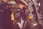
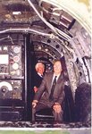
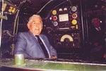
Here are a few shots of the surviving crew members of 625 Squadron Lanc "Oozlum Bird", shot down and PoW in July 1944, inside 'Jane', the Lanc at East Kirby, which might help with a few details. Note that no systems are yet connected to the electrical distribution panel at this time, May 1991. I'll see if I can find a shot of the panel in the BBMFs Lanc.
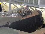
The last shot is a close up of the Duxford Lanc, showing how the connections and cables are visible through the starboard side window.
 

Attachments

  • Duxford  May 2011 053.jpg
    Duxford May 2011 053.jpg
    92.8 KB · Views: 145
  • Can Jan 557.jpg
    Can Jan 557.jpg
    96.6 KB · Views: 146
  • Can Jan 561.jpg
    Can Jan 561.jpg
    63.4 KB · Views: 146
  • Can Jan 559.jpg
    Can Jan 559.jpg
    95.1 KB · Views: 139
Great pics Terry, and fantastic work Gerry!

Hope to be able to see this in the flesh sometime mate - will know within 2 weeks if we move to the 'Emerald isle' or not!
 

Users who are viewing this thread

Back