**** DONE: 1/48 CAC CA-13 Boomerang - Aircraft Nose Art GB.

Ad: This forum contains affiliate links to products on Amazon and eBay. More information in Terms and rules

Pete, Im doing the 1/72 Special Hobby version. So far its been challenging, but also rewarding. Im having some difficulty with joining the fuselage halves, and the cockpit bath sits too deep in the fuselage. Thats caused the wing assembly to sit proud of the lower fuselage. Lots of fill and sanding required.

The good side is that the kit appears to be very accurate, and there is a lot of detail included.

ive not had any trouble with the canopy. My engine appears at least as detailed as the 1/48 version, which puts a nice smile on my face.

I really would like to get hold of the reference that you have. Whats the name of the book again, and where did you score your copy. i might look into it....
 
Hi Michael

Wayne's answered that one over on your build thread, but the book is called "The CAC Boomerang" by Richard A. Franks and published by Valiant Wings Publishing. Available direct from the publisher.

Okay, about time to start - don't you think?


Pic 1
Here I added the masks to the canopy. I used Montex masks, which are a vinyl type, rather than Kabuki tape masks. The fit is less than ideal, and not as good as I would usually expect from Eduard. The one advantage though, is that masks are supplied for both the interior and exterior of the clear parts.

Pic 2
Apart from the resin supplied, Special Hobby also provide this nice fret of photo-etch.

Pic 3
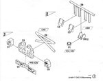
This is the Special Hobby parts diagram/ instructions showing the parts for the first sub assembly.

Pic 4
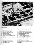
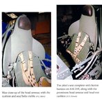
This is the section of the pilots manual that deals with the same area and describes each part.

Pic 5
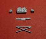
Parts needed for the first sub-assembly are removed and ready for assembly

Pic 6
This is the side panel. I made a couple of mods to add a circular indent to represent the Hydraulic Pressure guage and carved three slots for the Flap and landing gear indicators. That's items 53,54 and 55 on the pic 4.

Pic 7
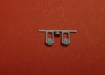
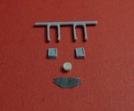
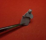
Assembly completed, with the exclusion of photo etch part pp20, which appears to be a duplication of the Oil Cooler and Shutter control lever (parts D3 D4), and cutting part pp21 in half as this appears to duplicate the Hydraulic Hand Pump Lever (Parts D2).


I'll put this assembly aside, ready for painting, and move on the next sequence.

Cheers

Peter
 

Attachments

  • etch 001.jpg
    etch 001.jpg
    47 KB · Views: 168
  • canopy 006 - resized.jpg
    canopy 006 - resized.jpg
    41 KB · Views: 173
  • sequence1 007- resized.jpg
    sequence1 007- resized.jpg
    123.1 KB · Views: 204
  • sequence1 006- resized.jpg
    sequence1 006- resized.jpg
    26 KB · Views: 197
  • sequence1 005- resized.jpg
    sequence1 005- resized.jpg
    40.6 KB · Views: 201
  • sequence1 004- resized.jpg
    sequence1 004- resized.jpg
    22.3 KB · Views: 164
  • sequence1 003- resized.jpg
    sequence1 003- resized.jpg
    43.8 KB · Views: 154
  • sequence1 002- resized.jpg
    sequence1 002- resized.jpg
    42.3 KB · Views: 195
Nice :D work for far :)

how large is the 1/48 Boomie compared to other kits? :) since shes mini in 1/72 :D
 
pete is a great model I did with the 1/72 and mate, this model I would like to buy it from and I will do so sooner rather than later fter more detailed see how it goes.
a great job you're wearing ...
 
You must really have Superhero levels of eyesight to do work like that - I'm getting dizzy just looking at the pics!
Thanks for your kind remarks, but......

I have cr*p eyesight and shaky hands, but I do have a bloody big magnifying glass and patience! That counts I guess. :rolleyes:

Pic 1
Ah..the next stages are to complete the rudder assembly and the instrument panel.

Pic 2 3
Rudder assembly is straight forward. Combination of injected, resin and photo-etch. Job done. Easy.

Pic 4
Instrument panel - different story. The instructions are a bit unclear how these all go together. The side panels are/were angled inwards on the real deal and there is no reference for how high the framework should be glued on the back on the panel. I'll put this step aside until I get to install in the cockpit proper, so I can tweek accordingly.

Pic 5 6
Cockpit side wall breaker/fuse panels and smaller panels are glued down. I'm trusting the instructions here, that they are going to appear in the proper locations through the tubular framework when that gets added.

Pic 7, 8 9
Seat armour plating and head rest are assembled, again straight forward. From the pic of the restored Boomerang, it was a substantial piece of armour protecting the pilot's back. The headrest was a dark brown leather.
 

Attachments

  • sequence5 003- resized.jpg
    sequence5 003- resized.jpg
    49 KB · Views: 150
  • sequence5 001- resized.jpg
    sequence5 001- resized.jpg
    40.4 KB · Views: 169
  • sequence4 002- resized.jpg
    sequence4 002- resized.jpg
    35.1 KB · Views: 185
  • sequence2 002- resized.jpg
    sequence2 002- resized.jpg
    51.6 KB · Views: 188
  • sequence4 001- resized.jpg
    sequence4 001- resized.jpg
    29.9 KB · Views: 192
  • sequence3 001- resized.jpg
    sequence3 001- resized.jpg
    76.3 KB · Views: 175
  • sequence2 001- resized.jpg
    sequence2 001- resized.jpg
    80.6 KB · Views: 173
  • sequence2-3.jpg
    sequence2-3.jpg
    41.9 KB · Views: 207
  • sequence5 004- resized.jpg
    sequence5 004- resized.jpg
    93.1 KB · Views: 220
Reminds me of the I-16 and its crapy wheel bays :D

I hope this Boomie is much easier to get together :) and stay in place :)

Looking great so far :)
 

Users who are viewing this thread

Back