**** DONE: 1/48 ICM Spitfire Mk IX AE-B Ian Keltie of 402 SQDN RCAF Commonwealth GB

Ad: This forum contains affiliate links to products on Amazon and eBay. More information in Terms and rules

Wings fully on now.

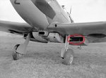
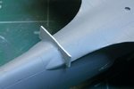
Pic 1 I cut a bit too much off the fuselage to fit the rear wing section so added this bit of plastic card as filler.
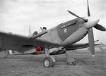
Pic 2 The gap at the wing roots. A bit of putty will fill this little gap.
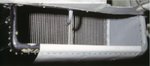
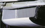
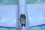
Pic 3 The wings from the top . Turned out not too bad and the dihedral has been maintained. A bit of light sanding and selective filling will clean this up. The gun hatches need to be sanded down at the edges as well.

The first of several steps of filling and sanding has started. May get a prime coat on tomorrow if all goes well. Thanks for checking in.
 

Attachments

  • 101211 Filler.jpg
    101211 Filler.jpg
    60.9 KB · Views: 79
  • 101211 Wing Fairing.jpg
    101211 Wing Fairing.jpg
    75.4 KB · Views: 80
  • 101211 Wing from Top.jpg
    101211 Wing from Top.jpg
    86.7 KB · Views: 80
Some nice efforts in overcoming some challenges(some are glutten for punishment :) ) with some nice effects in fit and the pit ;) Cheers
 
Thanks Aaron. Here's the result of today's work:

First off, I completed the pully cable for the harness in prep for closing the rear canopy. I know there's a rail at the top that should go in but to make it fit the canopy would need to be thinned down considerably so I'm leaving this off.

101212 Harness.jpg


Next, with the engine block omitted, the exhaust stacks had to be supported on the inside. The arrangement I came up with is shown below with spacers made from card and the struts between the exhausts cut to length from sprue and glued.

101212 Exhaust Supports.jpg


The next pic shows the nose section with the exhaust stacks in and the lower cowl in place. Unfortunatley there's a bit of a step to deal with where the various cowl panels meet. The round plate behind the spinner was filed down to fit properly in the hole before gluing this in. It will also need to be sanded flat to receive the spinner. Also seen in this view is the hole drilled in the port wing root for the fuel cooler.

101212 Nose.jpg


Next we have the finished rad covers with the linkages completed. The flanges on these covers had to be substantially filed down to eliminate the step where it meets the lower wing surface. These are shown before the thinning.

101212 Rad Linkages.jpg


Finally, here's the underside after various rounds of puttying and sanding. I noticed a few more sink marks in front of the flaps that were filled with primer and sanded smooth. A few more passes of putty are required to get the underside to my liking. The supercharger intake has been left off pending completion of the filling in this area.

101212 Underside.jpg


Thanks again for your interest.
 
Thanks Glenn. I agree with you and I may end up not sanding these down. They actually look worse in the photo with the shadow from the flash. We'll see.
 
Great job Andy, and thanks for the explanatory pics. It took some time for the pics to open, and for the bl**dy page to stop imitating a kangaroo, but it was worth it!
I should be ready to tackle the same stages soon, now that I'm up and about again.
 
Thanks Bill and Terry. BTW, I've been scouring my references and am trying to determine the configuration for the rad de-ice pipes. I have several clear pictures that seem to show the pipe in the starboard rad inlet only - nothing in port side. Is that correct? Also, the tube that is visible seems to be slightly off the centerline of the rad and slightly outboard.

See pics below of same aircraft. The first photo shows no tube in the port rad duct but it's clearly seen on the starboard duct on the second photo. I have the same evidence in a Topshots book on the MkXVI. Comments?
 

Attachments

  • FA_18357s De-ice tube.jpg
    FA_18357s De-ice tube.jpg
    76.8 KB · Views: 65
  • FA_18359s De-ice Tube.jpg
    FA_18359s De-ice Tube.jpg
    68.1 KB · Views: 60
It seems that the de-icer spray tube was in the starboard radiator covering only. Here two images of radiators of a Spitfire Mk.IX of the IWM Duxford. The nozzle was mounted rather centrally.
 

Attachments

  • Spit rad1.jpg
    Spit rad1.jpg
    34.9 KB · Views: 57
  • Spit rad2.jpg
    Spit rad2.jpg
    43.8 KB · Views: 52
Last edited:

Users who are viewing this thread

Back