**** DONE: 1/48 Spitfire IXc - Defense of Britain/Atlantic. (1 Viewer)

Ad: This forum contains affiliate links to products on Amazon and eBay. More information in Terms and rules

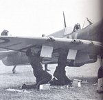
Couldn't find any clear photos of the outer gun positions but found a couple of photos of the IFF fuselage entry.

john.JPG
john1.JPG


Geo
 
Here's a pic of the .303 mg gun ports on a Mk.1 during the BoB, and on the World's oldest-surviving Mk1 at RAFM, Cosford. The ports were the same size and shape as those on later Marks. Note the remains of the fabric patches on the wartime example. .
As mentioned in my previous post, and confirmed by the Works drawing posted by Wojtek, the muzzles of the .303 Brownings were 'buried' in the wings, firing through 'blast tubes', and could not be seen (not without peering down into the shadows of the tubes,using a torch, anyway !)
On a 1/48th scale MkIX, the inboard gun muzzle would be approximately 1.5 to 2 mm inside the wing, and the outboard muzzle about twice that. Once you have drilled the holes for the gun ports, with the inside of the wing, and the ports, painted black, this will be more than acceptable.
Even if you mounted a 'blanking' panel inside the ports, or a tube to represent the muzzles, it will not be seen - I know, as I did it - once - on a 1/32nd scale model, and could have saved myself the time and effort !
Note that quite often, but not always,the area where the fabric patches were applied was bare metal, rectangular in shape, presumably to allow easier adhesion, and removal, of the fabric patches.
 

Attachments

  • Can Jan 830.jpg
    Can Jan 830.jpg
    78.3 KB · Views: 103
  • Cosfird Consvn Nov 13 092.jpg
    Cosfird Consvn Nov 13 092.jpg
    118.2 KB · Views: 105
Thanks Wojtek... that gives me the information I need to evaluate my choices! Those gun barrels ARE positioned quite deep. I was planning on leaving the outer gun ports open but adding barrels may not be worth it they aren't visible. I'll have to explore this later.
 
Thanks for the IFF photo, Geo! The square patch on the roundel of MH712 seems to match the position of the small round port in your picture Geo, if you line it up relative to the square hatch.

Regarding the de-icers... interestingly enough, the Eduard kit supplies ONE de-icer shown to be installed under the starboard wing but not under the port wing. It's a simple enough mod but I'm wondering why the omission. Did Eduard get fooled by the same pictures that I did?
 
As mentioned in one of my previous posts - yes, the 'patch' in your B&W photo is covering the redundant I.F.F. lead-in 'button', which is shown in the pics of the MkVb and MkIX I posted.
Note that the MkIX did not employ the I.F.F. wires from tail-planes to these buttons, having the MkIII I.F.F. rod antenna beneath the starboard wing. The 'buttons' were a 'left over' from the early MkV fuselages, which were completed as MkIXs on the production line.

I can't remember the specific details without checking my references, but the de-icer spray nozzle could be fitted to either the starboard, or both, radiator baths depending on production 'block' and engine fit, due to changes in the requirements for radiator area.
Originally, from memory, the port 'bath' housed only the enlarged oil cooler, and later, when extra cooling was required, this was changed to combine oil cooler and radiator, fitting another rad in the port bath, thereby increasing the radiator area without increasing the size of the 'bath'. This can be identified in photos, where visible, by what looks like a vertical 'bar' separating the two elements, which is, of course, the edges of the matrices of the two units.
So it's possible to see a MkIX with just one spray nozzle, in the starboard 'bath', or one in each rad 'bath'.
Again from memory, the MkXVI (Packard Merlin) had the spray nozzle in both 'baths'.
 
Onward ho! Work on the cowling continues. I'm taking lots of care and time here because I want a good result since the cowlng seam is in such a highly visible location. The cowling halves are glued together and then placed on the fuselage to check alignment. I'll let the cowling dry mounted on the fuselage and then take it off to address the seam.
IMG_8976_zpswhkbbn6x.jpg

IMG_8971_zpssgwq5uln.jpg


After sanding away the excess glue/plastic from the seam, I use a fine brush to apply Mr Surfacer 1000 as a filler.
IMG_8977_zpsvpkva403.jpg


The seam is carefully sanded and then polished. I repeated the process completely to get a satisfactory result.
IMG_8982_zpsq6nienyc.jpg


The fuselage seams are similarly addressed although very small amounts of filler were necessary due to the great fit.
IMG_8979_zpsehhtr54c.jpg

IMG_8980_zps6zmew5rh.jpg


Eduard and A Fascination with Fiddliness! This next section documents the building up of the wheel well walls. It's a morbidly complex affair comprised of FIFTEEN puzzle pieces not including the upper and lower wing parts. Engineering necessity of this procedure is called into question but alas, the modeler has no other course but to deal with what the manufacturer has given him. At least the parts fit well!

First the spar...
IMG_8983_zpsyyif3k0l.jpg


Then the four-piece box that houses the starboard landing gear receptacle...
IMG_8984_zpsw4xfcz31.jpg


Repeat for the port side...
IMG_8985_zpsy0hem4my.jpg


Three pieces form a ring around the wheel portion of the well...
IMG_8986_zpsifsyp9s2.jpg


The result give you a solid wall around the wheel wells with some nice details... worth the effort?
IMG_8987_zpsdq8kh7q4.jpg


The exhausts are another multi-part puzzle that makes you scratch your head. Each exhaust stack is comprised of four parts when most manufacturers can accomplish this with one. You'd accept this complexity, maybe even be thankful for it, IF AND ONLY IF, it gave you the ability to mount the exhausts after the painting. This is not the case. You must install the stacks BEFORE the engine cowling goes on and because the exhaust assembly is so complex, you can't modify the building order. So... you either leave the engine cowling unattached until after final painting or you have to mask and paint the exhausts AFTER the camo painting.
IMG_8988_zpshu8jl66z.jpg

IMG_8991_zpse3wsiqbk.jpg


Finally, I found out that the Hispano cannon ends were indeed hollowed out at the ends. But the less than perfect casting of these parts required a little more work with the x-acto blade to make them presentable.
IMG_8975_zpszicyls0e.jpg


Time to get some paint on some of these pieces!
 
Very nice John. Though there is great detail around the multi-part wheel well, Tamiya managed to add rivets deep inside the one piece nose wheel well on the Meteor. I also hate adding exhausts this early in the game but Eduard must have a reason.


Geo
 
My experience with Eduard is that they can be over-engineered but that the results, if you're careful, are generally positive. If you think the exhausts on this one are bad, the ones on their Bf110 are even worse. Each exhaust stub is a separate part and each needs to be glued to a plate. 24 little stub pieces and 4 plates. Sheesh!
 
My experience with Eduard is that they can be over-engineered but that the results, if you're careful, are generally positive. If you think the exhausts on this one are bad, the ones on their Bf110 are even worse. Each exhaust stub is a separate part and each needs to be glued to a plate. 24 little stub pieces and 4 plates. Sheesh!

I totally agree... that's it in a nutshell. Although fiddly, the fit of the puzzle parts is extremely good and when assembled with care, the results look darn good.

On to some painting... the wheel well area was primed in black and then painted in the same gray that will go on the bottom of the aircraft. The exhausts were also primed at this time.
IMG_8992_zpsrdd7lq09.jpg

IMG_9006_zpstgdnwvb3.jpg


Some other bits were painted at this stage. These are the landing gear pieces and the grills for the underwing radiators. Everything has been given a dark wash to highlight the detail.
IMG_8998_zpshr3qeufu.jpg


More fiddly bits! The underwing radiators are also multi-part deals. Instead of griping about it, I put my trust in the fit of the Eduard parts and glued them together one part at a time. It's almost impossible to dryfit this house of cards completely but thankfully, the part fit is exact and positively located.
IMG_9003_zps5zymu1yn.jpg

IMG_9004_zpsjvylda75.jpg


At this point, I decided to glue together the rounded chin using the fuselage as a jig. The seam will have be cleaned up but at least there are no small details to worry about.
IMG_9007_zpscavcobcl.jpg


The exhausts were painted in layers. After the base black, I used a Alclad Steel as the main color. I then gave them an overspray of Alclad Exhaust Manifold. The tips were misted with a mixture of Tamiya Red Brown and Red, with each stack isolated using a small Post-It. Finally the openings were touched by a spray of heavily diluted black. The pictures don't really capture the different shades on these small parts but hopefully, the final pictures with the good camera will show the subtlety of the finish.
IMG_9010_zpspwcdwjdz.jpg

IMG_9008_zpstdffzquy.jpg
 

Users who are viewing this thread

Back