**** DONE: 1/48 Spitfire IXc - Defense of Britain/Atlantic.

Ad: This forum contains affiliate links to products on Amazon and eBay. More information in Terms and rules

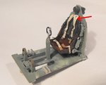
Thanks Terry! I just noted that the shoulder harness went over the seat not through the lower hole so I thought all is well!
 
Yep, you're right John.
I was thinking of the earlier Sutton harness, used on the MkI to MkV, which had the lap straps attached to the lower fuselage frame, and extra shoulder harness straps, beneath the 'main' shoulder straps and cables, which went over the back of the seat and down to the lower seat frame, behind the seat, as shown by the red arrow on my MkV seat. (the longer strap and cables are out of sight in this pic).
The MkIX had the later harness, with a quick release box replacing the pin and cone fastener, and just the longer 'Y' tail strap and cables, and is correct as on your model.
 

Attachments

  • J Kim.jpg
    J Kim.jpg
    35.6 KB · Views: 119
Just a quick note regarding that 'patch' in the roundel, shown in the B&W photos.
It appears that it is the old I.F.F. lead-in 'button', as, contrary to what I originally thought, the circular attachment was located in this position, as seen in the pics of the MkV and MkIX at Duxford.
The later I.F.F. antenna was a rod antenna, mounted beneath the starboard wing, just forward of the aileron hinge line, and outboard of the inboard hinge - if that makes sense!
If you need a pic and location drawing when you get to that stage, let me know and I'll post them here.
 

Attachments

  • Czech 045.jpg
    Czech 045.jpg
    95.7 KB · Views: 125
  • Czech 069.jpg
    Czech 069.jpg
    104.5 KB · Views: 115
Thanks for the info Terry! Photos would be helpful but I could use the photos to position the patch of color within the roundel. Those are great pictures BTW, especially in terms of color.

I got a little more work done on the Spitfire. The fuselage halves were secured using Tamiya liquid cement.
IMG_8963_zpscx2svtug.jpg


While letting the fuselage dry, I looked around for other minor sub-assemblies that I could work on. I decided on the prop. The prop assembly is the standard three-piece affair: the pointy spinner, the 4-bladed propeller and the spinner backplate. These three pieces fit together nicely but I noticed that the assembly didn't sit flush upon the circular mounting plate that is attached to the front of the fuselage.
IMG_8948_zpshjzna5ot.jpg


The backside of the spinner backplate has a raised circular portion on it. It's puzzling... obviously Eduard put some effort and expense to include this raised portion in their molds but why would they do that when it prevents a flush fit between the prop assembly and the fuselage?
IMG_8949_zpsavq50j4y.jpg


Anywhoo... it was a quick matter of using a flat sanding block to eradicate the offending plastic.
IMG_8950_zpsirikeguq.jpg


Now it sits flush as it is supposed to...
IMG_8951_zpsnvn2uhbr.jpg


The spinner itself got a little attention. I added some rivets using a sewing needle chucked into a pine vise.
IMG_8952_zps4b284mrw.jpg

IMG_8962_zps5hoiqjkg.jpg


One of the negatives that I've read about this particular kit is the upper engine cowling. It's supplied as two halves. Why not mold it as a single piece and eliminate that nasty seam in an obviously conspicuous location? While the fuselage halves are still taped, I tested the fit of the upper cowling pieces. It's a good fit but it's going to take a subtle hand to address the seam while preserving detail. I'll tackle this when I have more time.
IMG_8964_zpstnz8qqai.jpg


Moving on to the exhaust stacks. These are nicely detailed with supposedly hollow ends but upon closer inspection I find that one set has been mis-cast. See the flash on the upper one?
IMG_8965_zpscspd0zan.jpg


Cutting off the flash results in ends that are no longer hollow... doh!
IMG_8966_zpsakjwcilz.jpg


So I spend the next hour or so, hollowing out the exhaust tips manually using the tip of a sharp x-acto blade.
IMG_8968_zpstcwqr1sw.jpg


This work caused my hands to cramp up... have you guys experienced this when trying to grip tiny parts for long periods of time? I called it a night after this. To be continued...
 
Nice work John, and yes, cramped hands are a permanent problem for me, due to Rheumatoid Arthritis these days. Apart from being very uncomfortable and quite painful, it's also very frustrating when my hands won't do what I want them to do !
That 'spacer' on the back of the prop plate I can only think is there to simulate the slight gap between prop rear plate and cowling on the real aircraft, but perhaps slightly overdone.
If you'd like some close-up detail of the Spit MkIX, I'm going to the BoB airshow at Duxford over the weekend of 19th - 21st September, and will be escorting Jeff Hunt and Andy around the Museums on the Monday, when the airfield and hangars are 'back to normal' after the show. MH434 should be there, and If it's accessible (although normally only at 'arms length'), I can photograph whatever is required, if possible.
Just let me know which areas of the airframe you need shots of, and I'll see what I can do.
 
I agree with Terry on the back plate. The spinner is never exactly flush, though the gap should be small.

Spit Spinner.jpg
 
Last edited:
Another cool picture! Since the prop shaft simply sits in the hole (no glue if you want the prop to spin), the spinner should sit with a small gap between the backplate and the fuselage. The seam between the spinner and backplate is also noted.

The offer of photos from the museum is greatly appreciated Terry! A BoB airshow sounds like an awesomely fun event to attend... was the GB designed to correspond with this anniversary? I don't foresee any major modifications to this bird from this point but any pictures would be nice to see.

There is one area that I'd like a little more information, if anyone has any. The wing guns. Based on my superficial research, my MH712 is being modeled with the Type "C" wing, noted by the inboard placement of the faired Hispano cannon (is that the meaning behind the IXc designation?). The kit also features the slim upper wing fairing that denotes a single cannon in each wing versus dual cannons. So the stubby fairing just outside of the Hispanos was unused, hence the rounded cap on them?
spitfi7.gif


The outer gun positions are 0.303 inch machine guns. Does anyone have any pictures of these guns? I wanted to show the guns in the firing/just-fired condition, with the holes bored out and perhaps pieces of brass tubing to replicate the gun barrels but I'm not sure if the openings are circular. Are the red squares over these gun positions, temporary material to keep junk from entering the openings during take-off?
 
To answer the first question, yes, the 'C' wing was the 'Universal' wing, designed to accept two cannon per side. The domed cap on the 'stub' fairing covers the 'empty', unused cannon port, whereas on the 'E' wing, this 'stub' would be on the opposite side of the 'live' cannon, and would be the port for a .50 cal Browning, with the 'stub' lacking the dome, and being sealed by a patch of red-doped fabric, or a cardboard disc. ( the 'live' cannon muzzle would also have a cardboard cap on it, normally dull red, but this could also be white, or natural fiber coloured.)
The m.g. ports were quite large, in relation to the diameter of the .303 Browning barrel jackets, and were basically circular, although the curve of the leading edge of course meant that the 'holes' would look almost elliptical (see my MkV build).
The guns themselves were fully enclosed within the wing, and the muzzles could not be easily seen. The barrel cooling jackets had 'oval' cooling perforations, but again, unless the gun access hatches are open, the barrels can not be seen.
The gun ports, like the cannon muzzles, were sealed by doping fabric patches over them, hence the dull red colour of the 'squares' seen on the wing leading edges. These patches were to prevent the ingress of dirt and dust into the barrels when on the ground, and, perhaps more importantly, to prevent 'Damp Cold' - the formation and build-up of ice in the barrels and at the breach face, which would prevent the guns from firing, despite the heating ducts in the gun bays, which only heated the gun receivers.
When the guns were fired, the patches of course became torn and ragged, with propellant staining around the edges. When re-armed, the torn patches were removed, and new ones dope in place.

I think the GB was partly timed to coincide with the BoB anniversary, as we had a BoB GB a few years back. The airshow at Duxford, always a great event, and on a genuine BoB airfield, will be even more 'special' this year, with at least twenty Spitfires flying, and a re-creation of a BoB mass scramble.
Karl and I will be meeting-up with Andy (Crimea River) and Jeff Hunt, who are making the journey from Canada especially for this historic event, and we'll be touring the museums and hangars on the Monday after the two-day airahow.
 
TWENTY flying Spitfires??? That'll be an incredible sight to see AND HEAR! I love the sound of WWII-vintage fighters roaring through the sky!
 
I think it will be 19 now with the crash of MK912 at Biggin Hill last month.

The below pic shows the cannon as mounted in a port E-wing as you can see the MG next to it. Not sure it is of use to you.

cannon%20bay%20E%20wing.jpg


I'll also post these next two pics which I like for their clarity:

FA_18357s.jpg
FA_18359s.jpg


These pics are useful to show a feature not usually supplied on kits but easy to replicate and that is the little glycol de-icer tube upstream of the radiator grilles in both ducts.

A addition of a simple piece of L-shaped wire does the trick.
 
Last edited:
Thanks for the pictures Andy! I'm looking for pictures of the machine gun port openings on the wings to see how far back the actual gun barrels might be from the opening. I can just make out one of the covered ports in the last picture. What's more interesting about the picture is that it is from a Polish unit like my MH712 and it is very clear. Helpful and interesting details including dirt/wear on the bottom of the aircraft... the slipper tank... camo demarcation... brake line on the landing gear. Incidentally, I only see the de-icer thing under the starboard wing, not the port wing. Any more of these Polish Spitfire pics?
 
The Spit with the "Ż" letter at the front of the engine cowling under the spinner , was the Spitfire Mk. IX of 306 (Polish) Squadron coded UZ-Z. The series of pictures was taken in Northolt, 16 November 1942 for the press. There is a round dot over the individual letter "Z" – this was no coincidence, but conformed with Polish spelling of Żulikowski's name. The BS456 subsequently served with another Polish squadron, No. 316. On 22 August 1943, the unit flew a Ramrod mission over the Channel. In the vicinity of Rouen the Spitfire formation was attacked by a group of Fw 190s. Two Spitfires were lost, one of them being BS456 piloted by F/Lt Kurylowicz. Kurylowicz parachuted into the Channel and spent five days in his dinghy before being rescued by an RAF launch.

spitfire-ix-306-sqn-small-765717.jpg


306sqdn-spitfire9-uz-z-northolt-16nov42.jpg


306sqdn-spitfire9-uz-z-northolt-16nov42_.jpg
 
The de-icers were in both radiator ducts John and you can actually see the other one in the first pic. The clarity of this pics is the reason I sent them along and I don't have any others of your unit to my knowledge but will check. I'll also see what I have on the gun ports but you always could just model all 4 MGs with tape over them and not worry about seeing the muzzles.

EDIT: By the way, here's a close-up of the de-icer on a Seafire at a local museum. Unfortunately I have none of the MGs.

IMG_1861 reduced.jpg
 
Last edited:

Users who are viewing this thread

Back