**** DONE: 1/72 Supermarine Seagull V - Heavy Hitters II GB

Ad: This forum contains affiliate links to products on Amazon and eBay. More information in Terms and rules

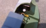
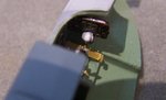
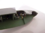
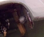
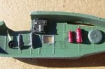
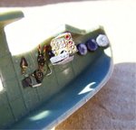
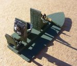
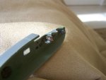
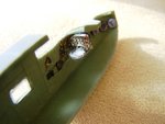
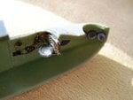
Here are the shots of the scratch built compass gimbal and the CP "black boxes" i built and fitted last night. The cockpit is ready for installation and the fuselage can then be buttoned up

as always, these extreme close ups really brutalize the work, but at normal magnificaton the scratch building looks quite good. im happy
 

Attachments

  • 102_2586.jpg
    102_2586.jpg
    88.2 KB · Views: 104
  • 102_2587.jpg
    102_2587.jpg
    45.9 KB · Views: 80
  • 102_2588.jpg
    102_2588.jpg
    46 KB · Views: 78
  • 102_2591.jpg
    102_2591.jpg
    52.2 KB · Views: 79
  • 102_2592.jpg
    102_2592.jpg
    50.5 KB · Views: 78
  • 102_2593.jpg
    102_2593.jpg
    47.6 KB · Views: 76
Very nice work indeed Michael, but that compass looks way too big!
Depending on the Model number of the compass, it measured approximately 6 inches in diameter, or smaller, and around four inches deep, or smaller. In 1/72nd scale that's approximately 2mm diameter. (easier to work in approximate mm rather than fractions of an inch, with such small dimensions.).
If you need them, I have some interior and exterior shots of the Walrus and Sea Otter, which were basically similar - just shout.
 
Great work Mike! Agree with Terry though, that compass does look way too big. (Easily fixed though!)

btw, I don't recall the thread title, but Matt (Matt 308 ) did a beautiful job of the Matchbox kit a couple of years back. Worth checking out his thread for details etc!
 
Very nice work indeed Michael, but that compass looks way too big!
Depending on the Model number of the compass, it measured approximately 6 inches in diameter, or smaller, and around four inches deep, or smaller. In 1/72nd scale that's approximately 2mm diameter. (easier to work in approximate mm rather than fractions of an inch, with such small dimensions.).
If you need them, I have some interior and exterior shots of the Walrus and Sea Otter, which were basically similar - just shout.


Im shouting.......would very much like to see what material you have....


It is too big, but not that easy to fix. I made it from an old lens I had lying about and it has a terrific glassy look when you look at it from above. I would be very loath to remove it and adjust it, because it is attached to a bracket I made up for it which passes under the IP. The Bracket is attached to the back of the IP. I didnt want to risk damaging the IP face by attaching the compass to it. Removing the compass now would be a difficult job.

I agree with your estimate of the diameter of the compass (6inches), but then the compass sits in a metal gimbal which adds about another 2-3 inches to overall diameter of the apparatus. My estimate is that the overall full size assmblky is about 200mm across. My 1/72 scale copy is 4mm which equates to 280mm (or 12 inches) if it were full size.

I could have done the thing in plastic sprue or similar, but I wouldnt have got the glass effect of the lens. It was a conscious decision that I made, perhaps a bad one.
 
Not a bad decision mate, very sound logic and still looks good!

My method would have been to make it from clear plastic, or cut a ring from correct diameter sprue or whatever, and paint the details. If wanting to add the glass effect, a THIN coat of Humbrol 49 varnish or 35 clear does the trick. Just watch the amount of shine you allow - too much will look out of scale in 1:72!

This is just by the by though, you've done a great job, keep up the good work! :thumbright:
 
I agree with Evan. Although the compass was within the gimbal, and on the mounting bracket, it was also recessed partly into the cut-out in the instrument panel.
The bracket you've made can be retained, and a new compass made as described by Evan, or alternatively, use a piece of plastic tube, filled with plastic rod but leaving a hollow, which can be painted and then filled in with a drop of PVA. This will dry clear, and look like glass. Note, however, that generally these instruments had a non-reflective glass, so that they could be read at an angle, and very often, when close to the real thing, it's difficult to tell if there's glass there or not!
You've done a great job on it, but it does look far too large and, by the time the pilot's seat and control column are fitted, it'll fill the space between, and could cause interference problems.
Below are a couple of pages from the Mushroom book on the Walrus and Stranraer, showing the cockpit and the compass, and I think you'll see the difference here.
The book is 39 MB, so too big to e-mail, but I can put it on CD an send it on the next passing pigeon, if you can wait that long, but I'll need a mailing address via a PM.
 

Attachments

  • Walrus 1.pdf
    1.2 MB · Views: 120
  • Walrus 2.pdf
    1.5 MB · Views: 70
Ive decided to have a go at re-doing the Compass. Terry is right....its way too out of scale (though it will fit into the space available fairly comforatably). But I need to go at this very carefully. To get the compass subassembly out of the cockpit, i will need to apply very carefully some debonder on the back of the IP where Ive attached the compass support bracket. I'll probably leave the debonder to do its thing overnight and then careflly pull the whole compass assembly out. It is going to be a very delicate operation.....I will apply the debonder with a very small brush I think. I absolutely dont want to damage the PE parts or the IP face. They are all VERY delicate and easily damaged.

Before I attempt that though I want to fabricate my replacement compass and support frame. I'll use some map calipers to get the width dimension as the compass rose is supposed to be partially in the recess at the bottom of the IP (we will see about that...maybe,maybe not). Based on the material Terry provided, and the advice given by A4, I should be able to make the compass support gimbal and the little black box at the base of the IP which I can then use to attach to the back of the IP. I have some questions, though....once I get the existing assembly out, and after say a few days, will the debonder residue (dried up by then I expect), cause any dramas in reattachment (Im still going to use CA glue...I have to basically hold the thing in pace with Forceps whilst it dries). Also when Ive used debonder in the past, its not been as constricted, which means I could use quite copious amounts. Here I will need to apply the stuff very sparingly, only onto the joint itself, and only from one side of the joint. Do you think that will make much difference....a comprehensive but sparing application of the debonder...?

What are your opinions guys...should I attempt this?
 
I would certainly try it, but I'm a detail nut. Up to you: if you think it's worth it - go for it! :)

I like that idea too Terry, will store it in the grey matter. Thanks for the PDF attachments too, copied and saved already!
 
I think the de-bonder should work just enough, applied sparingly. The good thing about CA is, it's a glue, and not a cement. This should (hopefully) mean that, once the joint is weakened, by de-bonder or pressure, it should 'give' and come apart. Any residue can be carefully removed with a scalpel blade.
 
Am back and have taken a few shots of the job. it took a lot of prearation, but the actua; job itself, once i kicked off, was pretty straight forward really

The next job is to put the PE turret rings into the firing positions. involves forming the PE strip as a curve. something ive never done before. Should be interesting.

anyway, what do you think? worth the trouble and fuss?
 

Attachments

  • 102_2597(ii).jpg
    102_2597(ii).jpg
    56.7 KB · Views: 60
  • 102_2597.jpg
    102_2597.jpg
    183.6 KB · Views: 64
  • 102_2599.jpg
    102_2599.jpg
    34 KB · Views: 65
  • 102_2600.jpg
    102_2600.jpg
    91 KB · Views: 59

Users who are viewing this thread

Back