Vic Balshaw
Major General
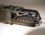
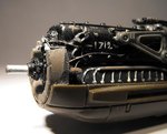
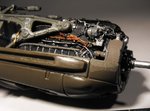
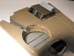
Looks good Terry, glad (with your ingenuity) the engine now fits
Follow along with the video below to see how to install our site as a web app on your home screen.
Note: This feature may not be available in some browsers.
Ad: This forum contains affiliate links to products on Amazon and eBay. More information in Terms and rules