**** DONE: Bf109E4 'White 6' I/JG3 BoB Group Build.

Ad: This forum contains affiliate links to products on Amazon and eBay. More information in Terms and rules
Not really mate, just using what's there, and enhancing a few things. Can't see the point in spending money to throw in bits of stuff that's already made and painted for you, by someone else, when the basics are there, and just need a bit of care. I just wish my stupid hands would work properly, so that I can do justice to this old kit - it's 33 years old and, apart from the standard of moulding from the era, can show some modern kits a thing or two !
 
The cockpit area is nearly finished, and it's almost time to close-up the fuselage.
I decided to use the kit part for the oxygen regulator after all, mainly due to a possible problem with fit if I scratch-built the item, due to the moulded side wall detail etc.
I reckon it'll be easier to build one into the 'bare' walls of the Hasegawa kit, so I added a few bits to the kit part for this build, more of which later.
I'm sorry the pics are a bit 'off', I just couldn't get the lighting right, I think because I'm tired and drained at the moment, as the arthritis is giving me grief, especially in the hands and ankles. Anyway, here's some pics of the progress so far. I think I could have done better in some areas, but it should look OK when it all comes together.
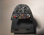
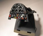
PICS 1 and 2. The instrument panel after glazing and adding the fuel pump and selector levers. The glazing on some instrument faces is still clearing here, and the sheen overall is due to the angle of the lighting - sorry !
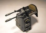
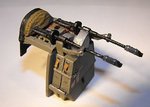
PICS 3 and 4. The guns and ammo tanks. There's still a bit of work to do on the front of the ammo tank bulkhead, which involves adding some relays and wiring, and this will be done once the assembly is installed in the fuselage. It's not very clear in these pics, but the cooling jackets of the MG17s have been drilled, as have the muzzle compensators.
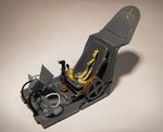
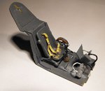
PICS 5 and 6. The main cockpit assembly, with the rudder pedals cleaned up, drilled, and the hoses and foot stirrups added.
The thin blue 'wire' on the starboard side is part of the oxygen feed system ,and matches up with the additions made to the regulator. The seat harness, made from metal foil and wire, has come undone on one side, the lap strap lifting away from the pad and buckle, and this will be fixed later.
PIC 7. Not a very good angle, but this shows the later style throttle lever with the pitch control switch on the end, and the yellow band indicating fuel. The other lever, with the yellow grip and thin red stripe, is the mixture control. After test-fitting the instrument panel assembly, I found I had to cut the carefully positioned push-rods leading from the three 'T' handles ! B*gg*r !!
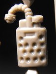
PIC 8. The kit part for the oxygen regulator.
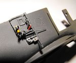
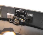
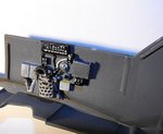
PICS 9 and 10. The regulator in place on the starboard wall. Again, not a very good angle, but the demand valve has been added, along with the plumbing and main feed pipe, and the regulator gauge has been drilled out, the calibrations painted, and the unit glazed. The perforations in the 'metal shield' have been drilled, to make them look more convincing, and the 'holes', and the top of the unit, painted a beige colour, to represent the canvas insulator. The shield itself was painted a metallic pale gold/silver colour, with a black data plate, and bare metal plumbing.
So, next stage is to install the rear wheel bulkhead, but I'll leave out the wheel assembly for now, for ease of handling during painting. Then the fuselage can be joined. The instructions advise that the wings etc are fitted next, but I'm going to experiment with fitting the engine assembly first, as test fitting indicates it could be tricky later, and it might be better to remove the oil cooler, and fit this once the engine is in place and set. Access should be possible via the opening for the housing and shutter.
Thanks again for your interest, and I'll post some more pics over the weekend.
 

Attachments

  • BoB Build 2 044.jpg
    BoB Build 2 044.jpg
    19.7 KB · Views: 103
  • BoB Build 2 047.jpg
    BoB Build 2 047.jpg
    20 KB · Views: 107
  • BoB Build 2 048.jpg
    BoB Build 2 048.jpg
    16.5 KB · Views: 102
  • BoB Build 2 050.jpg
    BoB Build 2 050.jpg
    19.5 KB · Views: 109
  • BoB Build 2 052.jpg
    BoB Build 2 052.jpg
    32.9 KB · Views: 105
  • BoB Build 2 056.jpg
    BoB Build 2 056.jpg
    36.3 KB · Views: 85
  • BoB Build 2 058.jpg
    BoB Build 2 058.jpg
    25.2 KB · Views: 101
  • BoB Build 2 022.jpg
    BoB Build 2 022.jpg
    16.3 KB · Views: 101
  • BoB Build 2 061.jpg
    BoB Build 2 061.jpg
    22.7 KB · Views: 87
  • BoB Build 2 064.jpg
    BoB Build 2 064.jpg
    21.7 KB · Views: 99
Thanks very much indeed guys. It's mainly the available kit detail, and I think I could have made a better job if my bl**dy hands still worked ! But, for what can be seen once the front and rear canopy sections are in place, it should hold up well enough.
 

Users who are viewing this thread

Back