**** DONE: Bf109E4 'White 6' I/JG3 BoB Group Build. (1 Viewer)

Ad: This forum contains affiliate links to products on Amazon and eBay. More information in Terms and rules

Thanks Chris and Karl. I should get the fuselage joined later, then play about with the engine installation. Next is the wings, radiators and tailplane. When it gets to the initial painting stage, I'll put it to one side, so as to start on the long job of correcting the Hasegawa '109. Seems like a sensible idea to get them both to the same stage, and do all the painting at the same time.
 
Thanks Lewis. This next lot is rather long, as I've taken some shots to show you (Lewis, that is) what to look out for around the nose section, which I'll cover in the points below. So apologies to everyone else if it gets boring !
The cockpit is in place and the fuselage joined, and I fitted the tail wheel, as per the instructions, after all. Having done a bit of fiddling to see if it could be fitted at a later stage, which it can, I decided my hands would struggle and, rather than spoil things later, I thought it better to fit it, and mask it when ready to paint the model.
PIC 1 shows the cockpit and gun assembly glued into the port fuselage half.
PIC 2. Before joining the fuselage, a piece of scrap plastic was glued inside the starboard half, covering the grease point, to avoid an empty hole on the outside later.
PIC 3. The fuselage joined, with no major problems - it virtually 'clicked' together.
PIC 4. There are a couple of sink marks and a slightly uneven joint beneath the nose, but nothing serious. This will be attended to before fitting the engine and wings.
PIC 5. Even if the cowling sections are to be glued in place, they must be test-fitted to check clearance over the guns and the gun feed chutes. It's really best to wait until this stage before finally fitting and cementing the gun support arms (Parts 57 58), so that the guns themselves can be adjusted as required to line up with the troughs in the engine cowling.
PICS 6 and 7. The test-fitting showed that some filing was needed around the troughs, and inside the cowling, to allow the muzzle sleeves to align and fit into the trough openings. Here, the port sleeve can just be seen inside the trough. The horizontal edges of the saddle cowling were also lightly sanded, to allow a better rebate onto the 'shelf' in front of the cockpit. It's a case of file and sand, test fit, file and sand, until it all sits correctly in place and aligns. This is even more important if it's intended to make the cowlings removable to show the internal detail, otherwise there will be prominent and unsightly gaps all round.
PICS 8 and 9. The saddle cowling has been glued together, after initial sanding, and placed into position to set at the correct angle. Once it is fully set,it will be removed, and further sanding will be carried out as required, to allow the edges to sit square. There will be a slight gap at the bottom edges of the upper cowl, and the lower extension cowl. However, once everything is aligned properly, thin strips of plastic will be cemented along the relevant fuselage areas, sanded to fit, and then blended into the background. This should give a neat fit all round. But bear in mind that, on the real aircraft, the joint between the main engine cowling and the saddle cowling was not perfect, and had a visible 'step' and slight gap at its upper rear face.
PIC 10. At this stage, it's important to check the fit and alignment of the windscreen against the top of the instrument panel and saddle cowling joint. Here, the screen is just placed in position, with the rear glazed section also, and the spacing is being checked to ensure that the opening section of the canopy will fit between the two parts correctly. In this instance, the main canopy section from the Hasegawa kit is being used, as the Matchbox example is very poor - a replacement canopy from 'Squadron' or Radu Briznan is recommended. Note that the Hasegawa canopy will look acceptable in the open position, but will not match the other sections' frame work accurately in the closed position.
Once satisfied that all the above have been taken care of, the next step, contrary to the instructions, is to fit the engine assembly, again checking clearance around the cowlings, before moving on to constructing the main wings.
Thanks again for your interest and compliments, and I'll post another update soon.
 

Attachments

  • BoB Build 2 072.jpg
    BoB Build 2 072.jpg
    36.5 KB · Views: 110
  • BoB Build 2 069.jpg
    BoB Build 2 069.jpg
    49.5 KB · Views: 119
  • BoB Build 2 086.jpg
    BoB Build 2 086.jpg
    25.6 KB · Views: 120
  • BoB Build 2 093.jpg
    BoB Build 2 093.jpg
    41.4 KB · Views: 119
  • BoB Build 2 076.jpg
    BoB Build 2 076.jpg
    55.9 KB · Views: 118
  • BoB Build 2 101.jpg
    BoB Build 2 101.jpg
    34.9 KB · Views: 120
  • BoB Build 2 098.jpg
    BoB Build 2 098.jpg
    50.6 KB · Views: 127
  • BoB Build 2 096.jpg
    BoB Build 2 096.jpg
    39.5 KB · Views: 117
  • BoB Build 2 079.jpg
    BoB Build 2 079.jpg
    62.5 KB · Views: 117
  • BoB Build 2 077.jpg
    BoB Build 2 077.jpg
    32.8 KB · Views: 120
Fantastic work Terry!

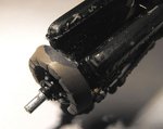
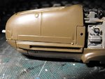
A question too - how come the brown trim wheel? I thought these were always painted in the interior colour?

If I am right from some of the photos I have seen it seemed to be trimmed in wood and Terry looking fantastic Sir :thumbleft: Cheers

Well A4k I just went and browsed some sites could not find a pic but I have seen it now at the Lair site I did find a G were it looked like some wood would be attached to the sides of the wheel to smooth out the feel for the pilot.I then saw another that was full on the sides so ??
 
Last edited:
FOR SALE: Daimler Benz DB601A engine, Serial No. 1712, brand new and complete, zero hours. Reason for sale - will not fit selected airframe !
Thanks very much guys. Evan, the inner wheel, for tail plane incidence adjustment, had a wooden trim over it, to improve grip, and also to differentiate, by 'feel', from the outer wheel, which was for the emergency lowering of the undercarriage. There were exceptions of course, especially with later, 'hurried' construction, and the wood trim often came off - a bit like some cars I know of !
Anyway, as you will all gather from the above 'advert', I'm having some problems fitting the engine assembly, and I recall having similar problems 20+ years ago, when I last built this kit.
Apart from a very tight fit and vague locating points, there is a lot of interference from the heavily moulded, internal locating pins in the lower fuselage. Fitting the assembly for permanent display with the cowlings removed would be acceptable, but if the cowlings are to be removable, or even fitted permanently, then some work is required to 'juggle' the engine, and bearers, into some sort of reasonable-looking position, and prevent the cowlings from 'popping' up.
So far, I've filed and sanded the rear of the supercharger housing, and the turbine casing, and removed the intercooler pipes from beneath the engine, and it's getting there. There are still gaps around the bottom of the main cowling though, and whether I'll be able to correct this without permanently glueing the cowling in position, I don't yet know.
Although the probability of ever displaying the engine, guns and ammo feed etc is slim, it would be nice to know that all the detail can be seen if required, so I'll continue to f*** about - er, sorry, experiment - to see what can or can not be achieved effectively.
At least it's some small consolation to know that even the Eduard '109 kits can not be built with a removable cowling - it's either on or off - so that eases the frustration slightly.
I'll try to get some detailed pics of the final outcome if possible, and thanks once again for your kind comments.
 
SALE WITHDRAWN.
It looks like I might be getting there!
More filing and cutting has been done to various parts of the engine, engine mounts and lower fuselage, and also a little more to the inside of the gun troughs and forward area of the main, upper cowling. After test-fitting, with the engine just placed into position and pushed down, but not glued, the upper cowling is starting to fit. I think that, if I can get it to stay the way it is, any small gaps can be shimmed with thin plastic strip, on the top of the lower fuselage rim.
Next step is to fit the engine, and cement and superglue it into the correct position. Once this has been achieved, then a few repairs can be carried out to the wiring and plumbing damaged during handling, and the removed parts cemented back in place. I doubt the intercooler pipes will go back in, but these can't be seen anyway, and the oil cooler bath can be fitted into the intake housing.
PIC 1. The ends of the mounting points on the upper engine bearer forks have been trimmed back, and the supercharger cylinder and turbine housing filed down flat. A small groove has also been cut into the ammo tank bulkhead, to allow the turbine housing to sit further back, without having to file the housing to destruction !
PIC 2. The bottom, rear edge of the Glycol tank has been filed, to help clear the lip inside the lower cowling.
PIC 3. The large locating pin mouldings, and the edge of the forward , lower cowling lip have been filed down. This was fairly hard work, as the plastic here is quite thick, and like armour plate ! The fuselage joint will be tackled from the outside, once the engine is set, and the fuselage and upper cowling aligned.
PIC 4. The inside of the main, upper cowling has been filed again, around the gun troughs, and also at the forward edge around the two small vents. A shallow channel has also been filed to the rear of each gun trough, to provide some clearance for the gun barrels and mounting arm brackets.
PIC 5. Test fitting the cowling with the engine loosely in place - almost there !
I strongly recommend disregarding the build sequence in ther instructions for fitting the engine, and do the work before the wings, or anything else, are fitted. This will allow ease of handling, easier access to the engine bay, and avoid probable damage to the wings and tail planes etc.
So, given this all comes together successfully, the next step is the assembly of the wings and radiators. I've got some photo-etched grilles left over from the Dragon P51 kit, which I might adapt and use in the radiators, if they look OK, so I'll post this stage soon, all being well. But first, I need to use the radiator housings to make patterns for a mould, in order to mould some housings for the Hasegawa kit for the other GB entry.
Thanks again for all the support.
 

Attachments

  • BoB Build 2 103.jpg
    BoB Build 2 103.jpg
    37.7 KB · Views: 120
  • BoB Build 2 107.jpg
    BoB Build 2 107.jpg
    33.9 KB · Views: 100
  • BoB Build 2 109.jpg
    BoB Build 2 109.jpg
    37.2 KB · Views: 99
  • BoB Build 2 112.jpg
    BoB Build 2 112.jpg
    36.9 KB · Views: 74
  • BoB Build 2 102.jpg
    BoB Build 2 102.jpg
    52.8 KB · Views: 98
Damn, I was going to buy that engine.

Your persistnece is definitely paying off with impressive results Terry. At least there's no danger that you'll file through the plastic!
 
Thanks Andy, and you're right about the plastic - it's as thick as a Hippocroccofrog's skin !
 

Users who are viewing this thread

Back