H.S. Buccaneer S2B, 12 Sqn., RAF, Lossiemouth, Scotland, 1985, Group Build. (1 Viewer)

Ad: This forum contains affiliate links to products on Amazon and eBay. More information in Terms and rules
With the MiG 21 set aside for now, I finally scraped together some semblance of enthusiasm to start on the Buc. One thing I'll need to do though, is to change the title date slightly, as the model will be displayed with Sea Eagle missiles (although I might convert them to radar Martels), which didn't start arriving on 12 Sqn until around 1988. I'm pretty sure I saw some in 1985, although they could have been trial versions, or radar Martel, the latter looking similar at a distance, but it's no big deal if I have to convert the kit missiles.
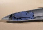
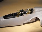
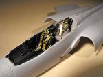
Anyway, the control column has been corrected, and a few bits and pieces done to the cockpit, including some re-painting and touch up. The engine turbines have been improved, as the 'bullet' fairings in the kit were far too small. The engine intakes were sawn in two, and the heads of some 1/72nd scale bombs used to represent the 'bullet' fairings over the turbine shafts, and then the intake tubes re-joined and glued.
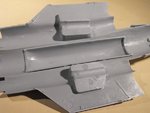
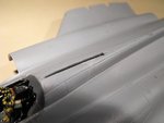
The bulged bomb bay cover for the rotating bomb bay has been glued in place in the lower fuselage half, and a decent amount of lead weight added in the nose, and a slot cut for the canopy guide in the upper fuselage half.
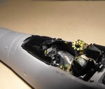
The cockpit is now in place, and the fuselage halves are ready to be joined - a job which I know is going to take time and a lot of patience!
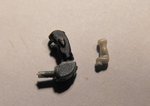
PIC 1 . The control column, removed from the instrument panel with, on the right, a new grip sourced from the spares box. I think the designer must have been looking at a 1/24th scale plan when he made the mould for this part!
The new grip has been attached to the column, which was trimmed down around the grip mount, and was painted and re-installed.
PIC 2. The intake joint after modification. Unfortunately, it was impossible to photograph the 'new' turbine after re-assembly, but this will be very visible on the finished model.
PIC 3. The inner face of the bulged bomb bay. Note the minimal, and very small, locating pins widely spread around the joining surfaces. Fitting the fuselage halves is going to be a right b*gg*er!!
PIC 4. Plenty of lead roofing flashing up front, held in place with 'Plasticine'.
PIC 5. The slot for the canopy guide rail cut into the upper fuselage.
PIC 6. Just visible here is the 'new' control column. There's still some touching up to be done to the seats, especially the firing handles, and some decals to add. This will be done when the masking is removed after painting.
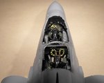
PICS 7 and 8. The cockpit in place, with the navigator's blast screen. The edge framing for this will be painted later.
PIC 9. A view into the cockpits, showing the navigator's seat offset to starboard.
PIC 10. The fuselage halves waiting to be joined. Tabs of plastic card will be cemented in strategic places around the inside edge of one half, to aid in alignment. Early releases of this kit were prone to warping of the fuselage, and my example, being one of them from 1994, is no exception, although not as bad as some I've seen. The joint will be made in stages, working from the nose aft, taping and allowing each stage to set, before proceeding. That's the plan anyway!
Thanks for your interest, and I'll post another update fairly soon.
 

Attachments

  • Buc build 017.jpg
    Buc build 017.jpg
    26.6 KB · Views: 94
  • Buc build 019.jpg
    Buc build 019.jpg
    18.2 KB · Views: 107
  • Buc build 025.jpg
    Buc build 025.jpg
    42.9 KB · Views: 118
  • Buc build 027.jpg
    Buc build 027.jpg
    25.3 KB · Views: 99
  • Buc build 028.jpg
    Buc build 028.jpg
    35.9 KB · Views: 112
  • Buc build 024.jpg
    Buc build 024.jpg
    23 KB · Views: 102
  • Buc build 033.jpg
    Buc build 033.jpg
    30.5 KB · Views: 103
  • Buc build 032.jpg
    Buc build 032.jpg
    41.8 KB · Views: 109
  • Buc build 031.jpg
    Buc build 031.jpg
    45 KB · Views: 100
  • Buc build 030.jpg
    Buc build 030.jpg
    32.8 KB · Views: 101
Thanks David. The blast screen was dual purpose; mainly to protect the navigator if/when the pilot ejected first, and secondly in case of the canopy shattering or being lost, possible on low-level operations. With a missing or holed canopy, there would be severe buffeting around the nav station.
 
WARNING ! Those of a nervous disposition are advised not to proceed further, and viewing of the images is strictly at the risk/discretion of the individual. No responsibility will be accepted for heart failure, injury caused through excessive laughter, or indictment for the use of abusive language!!!
Although the kit parts look good, and would appear to promise a nice model, this kit is an abortion!!!
Over the years, I've read or heard tales of the tricky to difficult job of joining the fuselage halves, and consoled myself with the fact that my example didn't appear to be too badly warped, and that almost fifty years of modelling experience should overcome such a minor problem.
However, I didn't account for the fact that the fuselage halves are made of a substance other than plastic, very possibly being Teflon, as they refuse to stick!
The use of polystyrene tube, liquid gel, and liquid cement has no effect whatsoever, and Plastic Weld just slinks away in fits of laughter. Resorting to desperate measures, I turned to Superglue as a 'save all' to at least hold key points whilst cement could be added to selected stretches of the joints, only to find that this material from another world repels the stuff faster than Jan downing a pint of Guinness on a hot day after a week of his pub being closed!!
Not wishing to admit defeat, I uttered a restrained 'Oh Dear', or something...er... similar, and persevered. After about an hour, I was able to join the nose section from the tip of the radome to the joint where the air-intake tubes locate, holding it tightly with tape until set, and accepting that the uneven joint would require sanding, filing and probably some filler later.
My plan of adding strips of plastic to aid in alignment quickly went to rat poo due to the inability of the plastic to remain stuck to the fuselage half, and I quickly discovered that the very small number of tiny, virtually ineffective locating pins would not align with their corresponding holes. So, having removed these, and sanded the mating faces of the joints in an effort to provide a 'key', I proceeded further, working in stages towards the aft end, and, after another hour, was able to achieve some semblance of a joint at the leading edges of the wing roots.
It was then that I discovered that the top half of the fuselage is 'out' by a little over 1 mm along its entire length, being longer from the wing leading edge to the opening for the speed brake at the tail!
So after almost three hours of struggle, a complete new dictionary of curses, and some calming coffee and cigarettes, I now have the fuselage joined, in a fashion, at the forward section, the leading edges of the stub wings, and one small length of the rear, starboard fuselage, the latter joint being highly suspect.
Oh, and there is now a new surface texture to the exterior, which I've dubbed 'Terra Cementus', which consists of various patina of mixed cements and glues, and resembles a rather barren, if rough, bleak landscape.
Thre's no particular order to the pics, taken during breaks to draw a deep breath, but they'll give an idea of what a shambles this job is so far.
Now, I'm going to the pub - I bl**dy deserve a pint, or several!!!
 

Attachments

  • Buc build 039.jpg
    Buc build 039.jpg
    52.4 KB · Views: 117
  • Buc build 040.jpg
    Buc build 040.jpg
    50.9 KB · Views: 120
  • Buc build 041.jpg
    Buc build 041.jpg
    50.1 KB · Views: 120
  • Buc build 042.jpg
    Buc build 042.jpg
    53.9 KB · Views: 102
  • Buc build 043.jpg
    Buc build 043.jpg
    37.8 KB · Views: 107
Glad that you didn't give up old boy! Although.....it has made me nervous about my Buccaneer now.

*Adds Guinness to the shopping list*
 

Users who are viewing this thread

Back