Good stuff Terry!
Navigation
Install the app
How to install the app on iOS
Follow along with the video below to see how to install our site as a web app on your home screen.
Note: This feature may not be available in some browsers.
More options
You are using an out of date browser. It may not display this or other websites correctly.
You should upgrade or use an alternative browser.
You should upgrade or use an alternative browser.
1/32 Spitfire Mk.Vb - Defence of Britain/Atlantic.
Ad: This forum contains affiliate links to products on Amazon and eBay. More information in Terms and rules
More options
Who Replied?- Thread starter
- #42
Airframes
Benevolens Magister
Thanks Wayne !
I've got the interior of the fuselage painted, along with the lower side walls and frames, and the first stage of painting the instrument panel and lower frame has been completed. The panel has reasonably good engraved and raised instrument and switch detail and, from past experience, the details should stand out if carefully dry brushed on some, and painted on others, before glazing with either Humbrol 'Clear', or possibly Humbrol 'Clearfix' for the 'deeper' dials.
Some of the instruments are actually moulded in '3D' where appropriate, and I'll try to show this when I photograph the finished panel.
Meanwhile, whilst waiting for the seat to dry, I'm currently tackling the other cockpit parts, such as the throttle quadrant (which needs the addition of a better throttle grip), radio remote selector, and the undercarriage selector, which will have the 'plumbing' added, using fine copper telephone wire. I hope to have some pics up sometime tomorrow.
The 'fun' will begin when I attempt to thread the HGW fabric Sutton harness straps through the PE buckles, and I suspect that, due to the state of my crippled hands, a lot of new curses will be invented !
I also suspect that some of the tiny PE parts will venture where no man has been before ...........................
Thanks Wayne !
I've got the interior of the fuselage painted, along with the lower side walls and frames, and the first stage of painting the instrument panel and lower frame has been completed. The panel has reasonably good engraved and raised instrument and switch detail and, from past experience, the details should stand out if carefully dry brushed on some, and painted on others, before glazing with either Humbrol 'Clear', or possibly Humbrol 'Clearfix' for the 'deeper' dials.
Some of the instruments are actually moulded in '3D' where appropriate, and I'll try to show this when I photograph the finished panel.
Meanwhile, whilst waiting for the seat to dry, I'm currently tackling the other cockpit parts, such as the throttle quadrant (which needs the addition of a better throttle grip), radio remote selector, and the undercarriage selector, which will have the 'plumbing' added, using fine copper telephone wire. I hope to have some pics up sometime tomorrow.
The 'fun' will begin when I attempt to thread the HGW fabric Sutton harness straps through the PE buckles, and I suspect that, due to the state of my crippled hands, a lot of new curses will be invented !
I also suspect that some of the tiny PE parts will venture where no man has been before ...........................
Hey Dogsbody, bring those seat belt things to Duxford and we can all have a go for you !
Looks good so far.
- Thread starter
- #44
Airframes
Benevolens Magister
I reckon they'll be either done, or scrapped by then mate !
fubar57
General
Good start Terry. Hoping the body cooperates with you.
Geo
Geo
Crimea_River
Marshal
Fantastic work Terry! I really like the way the lead foil represents the leather.
- Thread starter
- #47
Airframes
Benevolens Magister
Thanks George and Andy.
Had a bit of a mixed day today, so no more progress yet. But I'm just about to start work on it again, so might have some pics later.
Had a bit of a mixed day today, so no more progress yet. But I'm just about to start work on it again, so might have some pics later.
T Bolt
Colonel
Looking good Terry, good to have you back building.
- Thread starter
- #49
Airframes
Benevolens Magister
Thanks Glenn.
A few photos showing progress to date - apologies for the colour balance in most, one of my lamps popped a bulb, and the pics were taken in a mix of daylight and artificial light.
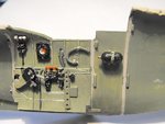
PIC 1. The starboard cockpit wall has had the kit parts added, and a scratch-built rack and spare reflector sight bulbs fitted, as well as the oxygen hose, the latter using a short length of the rubber-type, 1mm 'hose' from Model Design Construction, suitably painted, and with retaining clips added from tape.
I had actually attached the 'plumbing' for the undercarriage selector, using copper wire, but removed it temporarily, as it will b easier to fit and bend to shape once the instrument panel and floor are fitted - I hope !
The glare off the lights has caused reflections off the IFF destruct, distorting the stenciled wording, which is just dots and dashes of white paint, and the brutal macro shot has revealed some areas requiring re-touching.
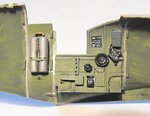
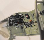
PICS 2 and 3. Port cockpit wall assembled and fitted, with a new throttle grip made from a short length of plastic rod, and the painted placard, again looking a bit rough in the macro shot - it looks acceptable enough to the naked eye. The VHF radio channel selector provided in the kit has only one row of 'buttons', and should also have a row of small, circular indicator lamps alongside each selector button. Unfortunately, the part was too narrow to try to replicate these, so it was left 'as is'.
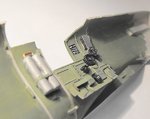
PIC 4. The 'floor' has been assembled with the rudder pedals, connecting rods and control column, with the latter having a brake lever added from stretched sprue. The 'floor' is a bit 'chunky' and basic, but once fitted in the depths of the cockpit, and with the seat in place, it looks fairly convincing and is acceptable enough.
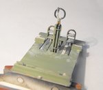
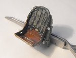
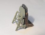
PICS 5 and 6. The seat has had the back armour and frame added, and the 'leather' back pad has been 'distressed' to represent worn and fading leather, in keeping with the age of the aircraft at the time depicted. There's still a little more work to do on the 'leather', to give it a sheen, and the seat and frame need some re-touching due to paint wear from handling.
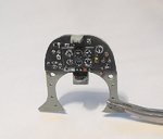
PIC 7. The instrument panel had the dials painted, and glazed with Humbrol Clear, but would benefit from another application in order to improve the appearance of the 'glass' in the dials. The compass was painted, and then the decal from the kit sheet added.
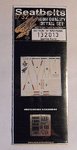
PIC 8. The next step is to fit the seat harness, using the fabric 'Sutton Harness' from HGW, which I'm sure is going to be a real barrel of laughs - not !!
Apart from some of the instructions being slightly vague, I have doubts about my ability to successfully thread the belts through the tiny PE buckles, given the condition of my crippled hands. I think I might end up adapting the belts/buckles for ease of assembly, which should still allow for an acceptable outcome, but we'll see what happens.
Once the harness has been fitted, and with the addition of some stretched sprue for the anchor wires running back to the mid fuselage, the seat and frame can be attached to the cockpit frame, the remainder of the cockpit assembled, and the fuselage joined.
Thanks again for the kind words, and I'll post another up-date soon - given I don't commit Hari-Kari in the middle of tackling the seat harness !
A few photos showing progress to date - apologies for the colour balance in most, one of my lamps popped a bulb, and the pics were taken in a mix of daylight and artificial light.
PIC 1. The starboard cockpit wall has had the kit parts added, and a scratch-built rack and spare reflector sight bulbs fitted, as well as the oxygen hose, the latter using a short length of the rubber-type, 1mm 'hose' from Model Design Construction, suitably painted, and with retaining clips added from tape.
I had actually attached the 'plumbing' for the undercarriage selector, using copper wire, but removed it temporarily, as it will b easier to fit and bend to shape once the instrument panel and floor are fitted - I hope !
The glare off the lights has caused reflections off the IFF destruct, distorting the stenciled wording, which is just dots and dashes of white paint, and the brutal macro shot has revealed some areas requiring re-touching.
PICS 2 and 3. Port cockpit wall assembled and fitted, with a new throttle grip made from a short length of plastic rod, and the painted placard, again looking a bit rough in the macro shot - it looks acceptable enough to the naked eye. The VHF radio channel selector provided in the kit has only one row of 'buttons', and should also have a row of small, circular indicator lamps alongside each selector button. Unfortunately, the part was too narrow to try to replicate these, so it was left 'as is'.
PIC 4. The 'floor' has been assembled with the rudder pedals, connecting rods and control column, with the latter having a brake lever added from stretched sprue. The 'floor' is a bit 'chunky' and basic, but once fitted in the depths of the cockpit, and with the seat in place, it looks fairly convincing and is acceptable enough.
PICS 5 and 6. The seat has had the back armour and frame added, and the 'leather' back pad has been 'distressed' to represent worn and fading leather, in keeping with the age of the aircraft at the time depicted. There's still a little more work to do on the 'leather', to give it a sheen, and the seat and frame need some re-touching due to paint wear from handling.
PIC 7. The instrument panel had the dials painted, and glazed with Humbrol Clear, but would benefit from another application in order to improve the appearance of the 'glass' in the dials. The compass was painted, and then the decal from the kit sheet added.
PIC 8. The next step is to fit the seat harness, using the fabric 'Sutton Harness' from HGW, which I'm sure is going to be a real barrel of laughs - not !!
Apart from some of the instructions being slightly vague, I have doubts about my ability to successfully thread the belts through the tiny PE buckles, given the condition of my crippled hands. I think I might end up adapting the belts/buckles for ease of assembly, which should still allow for an acceptable outcome, but we'll see what happens.
Once the harness has been fitted, and with the addition of some stretched sprue for the anchor wires running back to the mid fuselage, the seat and frame can be attached to the cockpit frame, the remainder of the cockpit assembled, and the fuselage joined.
Thanks again for the kind words, and I'll post another up-date soon - given I don't commit Hari-Kari in the middle of tackling the seat harness !
Attachments
fubar57
General
Beauty. Macro; like a b*tchy perfectionist, always there to point out your faults.
Geo
Geo
- Thread starter
- #52
Airframes
Benevolens Magister
Thanks Wojtek and Geo.
Haven't done anymore today, but I've just realised it's a Public Holiday in the UK tomorrow, so, as I won't be able to do all the 'domestic' stuff I'd intended to do in town, I should have most of the day to b*gg*r about with ... er, I mean assemble ... those seat belts, and maybe even get the cockpit fitted and the fuselage buttoned up.
Haven't done anymore today, but I've just realised it's a Public Holiday in the UK tomorrow, so, as I won't be able to do all the 'domestic' stuff I'd intended to do in town, I should have most of the day to b*gg*r about with ... er, I mean assemble ... those seat belts, and maybe even get the cockpit fitted and the fuselage buttoned up.
- Thread starter
- #53
Airframes
Benevolens Magister
I must have read a very inaccurate listing of UK Public Holidays - it's next weekend, doh !
So, I went about sorting all the domestic things I needed to catch up on, and will continue with the build as soon as I log-off from the forum.
So, I went about sorting all the domestic things I needed to catch up on, and will continue with the build as soon as I log-off from the forum.
Looks good Dogsbody
JKim
Senior Master Sergeant
Great work on the pit, Terry! I used fabric seats (RB Productions not HGW) on my 1/32 Erla 109G-10 build. They look nice but take some under the magnifier to thread those buckles on!
- Thread starter
- #56
Airframes
Benevolens Magister
Thanks mate.
I've just spent the last 2 hours working on the seat belts, and I'm only half way there !
Although very fiddly, threading the belts through the buckles wasn't as difficult as I'd thought - the tricky part was folding them over to glue them, using a tiny drop of 'Superglue'.
A little tip for anyone intending to use these HGW belts - thread the belts through the PE buckles with the PE parts still on the fret wherever possible, it's much easier !
Also, the instructions suggest that the belts, once cut along the dotted line (no dotted lines on my example!) should be 'crunched' up into a ball, then straightened out, no doubt to provide flexibility in the belts to allow a more realistic appearance when draped over a seat. I've found it's best to do this after fitting the buckles, as otherwise there'll be slight curves, and a certain 'springiness' in the fabric, which can be extremely awkward when working with them.
Just having a break to give my eyes a rest (!), then I'll get back to it and might have some pics later.
Crimea_River
Marshal
Looks great Terry. I wonder if the natural drape of the belts could be achieved by wetting them a bit after they have been loosely placed in the seat. Obviously the ink had better be waterproof.
- Thread starter
- #58
Airframes
Benevolens Magister
Thanks Andy.
Wetting them slightly may help with the 'drape', but once 'crunched' up and then straightened, they are a lot softer, and conform reasonably well.
The HGW instructions suggest a coat of matt varnish once assembled, but I presume this is to neutralise any 'sheen' from the surface.
I actually secured the free ends of each belt with a drop of 'Superglue' as they tended to want to lift just a little from the surface, where in 'real life', the weight and any buckles would make them hang, resting against the seat back, or lie on the seat pan. Once set, natural-looking folds or curves can easily be arranged.
I might yet give them a thin coat of acrylic paint or water colour, as the shade of the belts looks slightly pale for an earlier Sutton harness, especially given the age of the aircraft at the time depicted, when they would probably have been even darker due to soiling from use.
Anyway, on with the progress report.
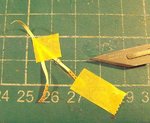
PIC 1. After adding the buckles to the main section of the shoulder harness, it was taped to the cutting mat to prevent it moving around whilst fitting the 'pull down' adjustment straps, which had to be fitted at the top of the darker section with the printed representation of the adjustment grommets, and then the buckle was slid down the main strap and secured to the top of the very short 'adjustment' strap, the latter having a tiny PE 'end cap' on the end of the strap - a very fiddly exercise indeed, despite a magnifying glass, and especially with crippled hands and 63 year old eyes !
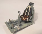
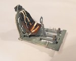
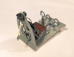
PICS 2 to 4. The harness in place, and the seat and seat frame attached to the cockpit frame. I cheated a bit here, and omitted the tiny lanyards and release pin and cone, partly due to their very small size and the difficulty and discomfort that would cause attempting to cut, assemble and fit them, and partly as I thought they'd be tricky to 'drape' convincingly, and probably wouldn't be seen anyway, once the fuselage was joined.
The same is true of the smaller 'Y' strap, which attaches to the bottom of the seat frame at the rear, where I omitted the mounting plate, which wouldn't be seen anyway, and attached the belt directly to the center frame instead, to allow more 'leeway' when arranging the belts later.
Note that this section of the harness drapes over the back of the seat, and not, as seen in some instructions and on many models, through the lower slot in the back of the seat.
The 'tail' strap has yet to have the Bowden cable shackle and cables fitted, which will be made from either a spare piece of PE, or fabricated from plastic card, with the cables from stretched sprue, or maybe 'invisible' mending thread, suitably painted. Once the cockpit assembly has been fitted, the 'cables' will be routed over the cross brace of the rear cockpit frame, and secured inside the fuselage at the frame 15 location. There was often a third cable, attached to the longitudinal brace beneath the rear glazing, supporting the harness cables, to prevent the harness falling down into the fuselage when not in use, but whether I'll fit this depends on accessibility when I reach that stage !
The lap straps have been attached beneath the seat, and not to the side of the seat or seat frame, as this was a later modification on the QS harness. The earlier Sutton harness lap straps were attached to strong points on the lower fuselage structure but, as this was not possible due to the method of assembly of the model parts, they have been positioned to present the correct appearance and, as the ends can't be seen anyway, they should look convincing enough once the fuselage halves have been joined.
PIC 5. The kit instructions call for the instrument panel to be fitted to the cockpit floor but, as I still need to re-attach the 'plumbing' for the undercarriage selector, which routes around the lower frame of the panel, if the floor was fitted, access to the selector would be virtually impossible. Therefore the panel has been fitted to the starboard fuselage half, along with the rear cockpit frame.
Next step is to fit the harness cables and the undercart plumbing, then fit the cockpit assembly, position and attach the rear ends of the cables, and make and fit the longitudinal brace between the back of the cockpit frame headrest and the rear cockpit frame. Once that's all done, the fuselage can be joined.
Thanks again for your interest and kind comments, and I'll post some more soon.
Wetting them slightly may help with the 'drape', but once 'crunched' up and then straightened, they are a lot softer, and conform reasonably well.
The HGW instructions suggest a coat of matt varnish once assembled, but I presume this is to neutralise any 'sheen' from the surface.
I actually secured the free ends of each belt with a drop of 'Superglue' as they tended to want to lift just a little from the surface, where in 'real life', the weight and any buckles would make them hang, resting against the seat back, or lie on the seat pan. Once set, natural-looking folds or curves can easily be arranged.
I might yet give them a thin coat of acrylic paint or water colour, as the shade of the belts looks slightly pale for an earlier Sutton harness, especially given the age of the aircraft at the time depicted, when they would probably have been even darker due to soiling from use.
Anyway, on with the progress report.
PIC 1. After adding the buckles to the main section of the shoulder harness, it was taped to the cutting mat to prevent it moving around whilst fitting the 'pull down' adjustment straps, which had to be fitted at the top of the darker section with the printed representation of the adjustment grommets, and then the buckle was slid down the main strap and secured to the top of the very short 'adjustment' strap, the latter having a tiny PE 'end cap' on the end of the strap - a very fiddly exercise indeed, despite a magnifying glass, and especially with crippled hands and 63 year old eyes !
PICS 2 to 4. The harness in place, and the seat and seat frame attached to the cockpit frame. I cheated a bit here, and omitted the tiny lanyards and release pin and cone, partly due to their very small size and the difficulty and discomfort that would cause attempting to cut, assemble and fit them, and partly as I thought they'd be tricky to 'drape' convincingly, and probably wouldn't be seen anyway, once the fuselage was joined.
The same is true of the smaller 'Y' strap, which attaches to the bottom of the seat frame at the rear, where I omitted the mounting plate, which wouldn't be seen anyway, and attached the belt directly to the center frame instead, to allow more 'leeway' when arranging the belts later.
Note that this section of the harness drapes over the back of the seat, and not, as seen in some instructions and on many models, through the lower slot in the back of the seat.
The 'tail' strap has yet to have the Bowden cable shackle and cables fitted, which will be made from either a spare piece of PE, or fabricated from plastic card, with the cables from stretched sprue, or maybe 'invisible' mending thread, suitably painted. Once the cockpit assembly has been fitted, the 'cables' will be routed over the cross brace of the rear cockpit frame, and secured inside the fuselage at the frame 15 location. There was often a third cable, attached to the longitudinal brace beneath the rear glazing, supporting the harness cables, to prevent the harness falling down into the fuselage when not in use, but whether I'll fit this depends on accessibility when I reach that stage !
The lap straps have been attached beneath the seat, and not to the side of the seat or seat frame, as this was a later modification on the QS harness. The earlier Sutton harness lap straps were attached to strong points on the lower fuselage structure but, as this was not possible due to the method of assembly of the model parts, they have been positioned to present the correct appearance and, as the ends can't be seen anyway, they should look convincing enough once the fuselage halves have been joined.
PIC 5. The kit instructions call for the instrument panel to be fitted to the cockpit floor but, as I still need to re-attach the 'plumbing' for the undercarriage selector, which routes around the lower frame of the panel, if the floor was fitted, access to the selector would be virtually impossible. Therefore the panel has been fitted to the starboard fuselage half, along with the rear cockpit frame.
Next step is to fit the harness cables and the undercart plumbing, then fit the cockpit assembly, position and attach the rear ends of the cables, and make and fit the longitudinal brace between the back of the cockpit frame headrest and the rear cockpit frame. Once that's all done, the fuselage can be joined.
Thanks again for your interest and kind comments, and I'll post some more soon.
Attachments

Great stuff, those belts look good
Users who are viewing this thread
Total: 1 (members: 0, guests: 1)