1/32 Spitfire Mk.Vb - Defence of Britain/Atlantic.

Ad: This forum contains affiliate links to products on Amazon and eBay. More information in Terms and rules
Thanks Wayne - it's not up to the standard I'm used to achieving as in parts, but that's down to these knackered hands of mine these days !
 
Wow Terry, that is one nicely detailed office mate and thanks for the tip re seat belt buckles, got me a set of these for the 109 and they sure look good.
 
Well, not that much to show for over five hours work, but some progress has been made !
The longest job was drilling-out the remains of the moulded cannon barrels, and I'll explain why in the section covering this below.

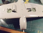
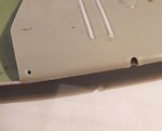
PIC 1. As the brass cannons from 'Master' are so nice, with open muzzles, it would be a shame to cover them with representations of the red, or sometimes white, cardboard caps fitted over the muzzles, which prevented dust and dirt entering the barrels, and also prevented freezing in the barrels at altitude. Therefore, after sanding down the moulded 'fabric patches', the gun ports were drilled-out, larger than the actual diameter of the gun barrels, as on the real aircraft. The 'fabric patches', applied for the same reasons as above, will be added after painting the model, using the tissue from decal covers, and pierced to represent the torn fabric after the guns have been fired. The red-brown stain seen on the wing is the result of the drill-bit slipping, and piercing my finger !!!
PIC 2. On the left, the opening for the gun camera has been counter sunk, and awaits clean up, whilst to the right, the holes have been drilled to accept the brass cannons. The 'Master' instruction sheet suggests using a 3.5 mm drill bit for this job. However, that's quite a large drill, in comparison to the thickness of the wing, and, if used, there was a very real risk of splitting, or cracking the wing across the chord, and / or the leading edge, especially as the solid stub of the moulded cannon was still on the upper wing half, inside the wing.
I therefore started a pilot hole, using a .75 mm bit, then progressed to a 2 mm bit, before continuing the slow and laborious task of filing the hole with a needle file, reaming with the tip of a scalpel blade, followed by more filing, whilst also filing across the hole, to ensure it was even all round. The edges were then thinned-down, again using the tip of the scalpel blade, and checked for fit with the brass cannon - it's important not to make the holes too large, or alignment of the cannons will be difficult, if not impossible.
It was at this stage that a loud cry of "**** !" could be heard anywhere in North West England as, when pushing the barrel carefully into the hole, I pushed too hard, and it fell inside the wing!
The wing root joint was carefully prised apart, the brass barrel retrieved, and the wing root cemented again.
Mishaps aside, if anyone is considering using brass barrels, either on a MkV or later Marks such as the MkIX, in any scale, I'd suggest using a similar method, to avoid serious damage to the wings.
The brass barrels will be lightly marked where they are to meet the leading edge of the wing, and fitted once the wing has been fitted to the fuselage, in order to simplfy alignment fore and aft, and vertically.
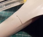
PIC 3. The method of joining the upper and lower wing halves leaves an unwanted joint line along the length of each aileron. There is a 'panel line' here on the real aircraft (with metal ailerons), but not this visible.
PIC 4. So the joints were sanded down, filled with 'Superglue', and sanded once more. They'll be checked, and re-sanded if required, after priming the model.
PIC 5. The hinge line of the flaps, and the aileron joints, were accentuated, using a razor saw, and await clean-up in this shot.
PIC 6. The wing in place, and clamped at the forward root, taped at the rear of the 'gull-wing' whilst setting.
PIC 7. Overall, the fit of the wing is quite good, with minimal filler needed at the rear joint - thinly stretched sprue should do the job - and just a little sanding along the upper wing root.
PIC 8. Oil cooler intake in place, and the lower engine cowling fitted. This had the distinctive panel joints of the oil tank engraved, and the fastening 'buttons' marked with the tip of a drill bit, and these will be enhanced at the painting stage. The oil cooler intake often had a horizontal bar just inside the circular opening - either a brace, or ice guard - but this was impossible to fit due to the nature and shape of the moulded part.
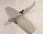
PIC 9. How the model looks so far.

All being well, I hope to make more progress tomorrow, perhaps up to the initial painting stage, and I'll post more pics then. Meanwhile, many thanks for the kind words and encouragement - very welcome when I struggle with these bl**dy stiff fingers and painful wrists !!!

EDIT:- Corrected last pic caption to oil tank instead of glycol tank - brain fade !
 

Attachments

  • DSCF0002 (7).JPG
    DSCF0002 (7).JPG
    37.6 KB · Views: 66
  • DSCF0004 (3).JPG
    DSCF0004 (3).JPG
    41.7 KB · Views: 64
  • DSCF0006 (5).JPG
    DSCF0006 (5).JPG
    56.1 KB · Views: 60
  • DSCF0008 (5).JPG
    DSCF0008 (5).JPG
    57.8 KB · Views: 66
  • DSCF0018 (2).JPG
    DSCF0018 (2).JPG
    42.4 KB · Views: 78
  • DSCF0012 (4).JPG
    DSCF0012 (4).JPG
    73.7 KB · Views: 64
  • DSCF0017 (2).JPG
    DSCF0017 (2).JPG
    47.1 KB · Views: 62
  • DSCF0019 (2).JPG
    DSCF0019 (2).JPG
    55.7 KB · Views: 69
  • DSCF0020 (2).JPG
    DSCF0020 (2).JPG
    30.8 KB · Views: 68
Last edited:
Thanks Andy. And yes, thank heavens for 'test fitting', which, incidentally, is a 'must' for those intending to fit brass cannons.
As the final 'fix' uses CA adhesive, it's important to ensure a good, snug fit, but with a little 'lee way' to allow for adjustment, as once the CA is applied, there'll be very little time to correct any errors in alignment - so fit (using a reference mark lightly scratched on the barrel to ensure correct length, shown on the instructions), align and check, then apply the glue, insert to the mark, and quickly align and check again.
I'm intending to wrap a thin strip of tape around each barrel, outside the reference marks, to prevent the barrels from a) being inserted too far, and b) to prevent the bl**dy things from falling inside the wing again !!
I had thought of doing this before the wing was fitted to the fuselage, but I think it's better to do it after fitting, as this will allow for more accurate alignment in relation to the wing chord, and to the center-line of the fuselage and horizontal datum, to prevent each barrel from being 'skewed' in/out and up/down.
Any remaining gap around the joints can be filled with CA, and carefully sanded to represent the collar and reinforcing plate, the latter already being moulded on the wings.
 
Last edited:
Thanks Wojtek and Wayne !
Nothing much to show, as the work has mainly involved attending to joints.

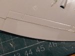
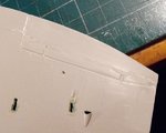
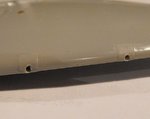
PICS. 1 and 2. The joint at the rear of the lower cowling needed filling. Although there is a rivet line here on the real aircraft, there wasn't a prominent panel line, so the joint has been filled by laying-in some thinly stretched sprue, and 'melting' it into the gap using liquid cement. Once set, it was trimmed and then sanded, with the sanding in progress in the second pic. A line of rivets will be added here, after priming, using a 'ponce wheel' riveting tool.
PICS 3 and 4. The same process was used for the joint at the rear of the 'gull-wing' fillet. A little more sanding and polishing is still required and if, after priming, the joint is still visible, then it will be treated by applying a thin bead of CA adhesive, followed by further sanding, and then re-primed.
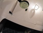
PIC 5. The rather prominent landing lamp covers, designed to be cut out and posed open if desired, will have a similar treatment, although the 'panel lines' will be retained, by laying in the sprue and etching around it. Alternatively, I may use 'Milliput' to fill the lines, then re-engrave.

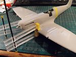
In the photo of Stan's aircraft, it's shown with the smaller (35 gallon ?) 'slipper tank' in place beneath the fuselage. Although the Hasegawa kit provides the much larger 'ferry' tank, this was not normally used on UK-based aircraft, so it's not much use here. There is a resin tank available, but at a cost, so if I eventually decide to fit the tank, I'll probably make a balsa male 'master' mould, and form one from plastic sheet. This would need to be done at this stage, so as to be able to test-fit and adjust both the master, and the first 'rough' moulding, without interfering with, or damaging any other parts of the model, if it were painted and completed.
I'll have to think about this, as I'd prefer to have the aircraft 'clean', although it would be nice to have the model the same as the photo.
Anyway, more up-dates to follow when there's something worth showing.
 

Attachments

  • DSCF0001 (6).JPG
    DSCF0001 (6).JPG
    46.3 KB · Views: 66
  • DSCF0006 (6).JPG
    DSCF0006 (6).JPG
    48.8 KB · Views: 71
  • DSCF0003 (6).JPG
    DSCF0003 (6).JPG
    32.1 KB · Views: 67
  • DSCF0009 (6).JPG
    DSCF0009 (6).JPG
    42.6 KB · Views: 76
  • DSCF0011 (6).JPG
    DSCF0011 (6).JPG
    44 KB · Views: 68
So, "attending to joints" would be MEDICAL marijuana I take it?

Terry, I found the slipper tank to be fairly easy to make out of sheet styrene, even though it was 1/48 scale. I still have a scale drawing somewhere too if you need it.

110101 Slipper Tank 2.jpg
110101 Slipper Tank 3.jpg
110101 Slipper Tank 4.jpg
110101 Slipper Tank 5.jpg
110102 Slipper Tank 6.jpg
110102 Slipper Tank 7.jpg
110102 Slipper Tank 8.jpg
 
Thanks chaps.
Andy, I'll have a think about the tank - does that make it a 'Think Tank'? (Coat, and hat, are near the open door !)
As the tanks were normally only fitted for escort or fighter sweeps, that doesn't really fit the 'Defence of Britain' theme, and when the Squadron was on defensive duties, the tank wouldn't normally be fitted.
There's time yet, but, as I think I'd prefer to show the lines of the aircraft without 'extra bulges', especially in comparison to my other 1/32nd scale Spits, and I really want to make this build as simple and quick as possible, in order to 'get back into the swing of things', and complete other, unfinished projects, I'll probably not bother with the tank, but add the attachment shackles etc on the underside.
I should have a little more to show later tonight, with the sanding completed, and the cannons and tail-planes added.
 
Great work on the joints! I like the stretched sprue method you used to seal the lower cowling... it looks like a good method for many situation. I'll have to keep that one in mind. It's also interesting to see the raised panel lines on this model. Great info on the scratched slipper tank too!
 

Users who are viewing this thread

Back