1/32 Spitfire Mk.Vb - Defence of Britain/Atlantic.

Ad: This forum contains affiliate links to products on Amazon and eBay. More information in Terms and rules

Thanks John.
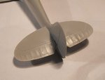
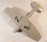
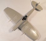
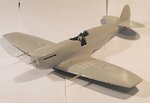
The raised panels lines are acceptable enough on most of the model, as the real aircraft employed lapped and butt-jointed panels in many areas. The raised lines of the kit are very fine and subtle, and look good enough under a coat of paint.
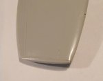
However, those areas where a more 'prominent' look is required, such as the cowling joints, have had the panel lines removed, and then engraved lightly - not too deep, as the Spitfire had a very smooth surface in general, and these will not be over-accentuated, as often seen on some models.
 
Terry that is a marvellous way to fix a problem Ive always had problems with. Ive always just tried to bodge it by using liquid putty, which works, but never as neat and seamless as that. Once Im done with the "this day in Europe thread", and get back into the model making, I know Ill be trying to perfect that myself
 
Thanks Michael.
It's a relatively quick, easy and effective method of filling fine to small gaps, and the sprue can be 'welded' into the gap, by carefully applying thin, liquid cement into the gap, and onto the sprue itself, then, when the sprue has softened, pressing it into the gap with the flat of a scalpel blade, allowing it to set before sanding, the latter being done with fine wet 'n dry - I used 1200 grit in this instance.
Where the gap is shallow, set the sprue into it, leaving it standing slightly 'proud' of the surface until set, and then trim, if possible, with a sharp scalpel blade, and then sand.
If only just 'proud', as it was with my model, then just sand until flush and smooth, polishing the surrounding area if needed - toothpaste, or better still, liquid metal polish or car-body colour restorer (T-Cut is a UK brand) is ideal for this, and is just as good, if not better, than expensive, branded 'plastic polish'.
For slightly larger and / or deeper gaps, particularly on relatively 'flat' surfaces, such as wing roots, then a strip of plastic card, or ready-cut plastic strip, can be inserted as far as it will go, cemented again using thin liquid cement, allowed to set, then trimmed and sanded as required.
If any cement should get onto the surrounding surfaces, do not try to remove this immediately - it will have softened the surface, and attempts to rectify at this stage will distort the surface, resulting in an ugly 'divot'.
Wait until the 'stained' area has fully set, and then lightly sand and polish, to restore the smooth surface.
 
Yep - unless you drop the carefully sharpened compass point you were about to re-insert into a spare pine-vise, and then can't find the bl**dy thing on the carpet, in the shadows under the work bench, and are too bl**dy stiff to get down to look properly !
Oh, give me a ******* break !!!
 
Yep, it's been one of those weeks!
It almost continued too - I settled down at the bench at around 17.30 hrs yesterday, thinking I'd get a couple of hours work done, before having a break for a meal, and then continuing for the rest of the evening. Then a friend called in, and even though he could see I was busy, insisted on 'hanging around', despite my polite hints, until 19.30 hrs !
By the time I'd cooked, eaten and washed-up, it was 21.00 hrs. I'd just settled down again, when the same bloke 'phoned me, asking if I could "look-up something on the computer" !
Bl**dy cheek - he keeps calling in, asking me to check on the value of cr@p he's bought at charity shops, even though he bought a computer over a year ago, which has been sat in it's box ever since, as he's too wary of paying for Internet service by Direct Debit !!

Anyway, I finally got down to some modelling at around 22.00 hrs, and made some good progress. There's just a few small things to do now, outlined below, before clean-up and preparation for spraying a primer coat overall. Once that's done, such things as joints and seams can be checked and corrected as required, and then the first coats of paint can be applied.
The pics show the work done to date.

PIC 1. The oil cooler intake and carb intake have been fitted, and the joints sanded and polished. Just outboard of the carb intake, on either side, small depressions have been countersunk, to represent the recessed jacking points, whilst forward of this, on the starboard wing (on the right as viewed), a small vent / drain hole has been drilled. A line of rivets has been added to the rear of the lower cowling, using the tip of the sharpened compass point (retrieved from the black hole beneath my desk!) which was pressed into the stretched sprue used to fill the joint.
The shackle hooks, deflectors and fuel feed valve for the 'slipper' tank have yet to be added, just aft of the jacking points, and forward of the I.D. lamp respectively. These will be visible, as I've decided not to make and fit the tank after all.
PIC.2. The tail planes have been fitted, after enhancing the trim tabs and actuators, and improving the hinge-line of the elevators.
PIC 3. The 'clipped' wing tips have been fitted, after cutting out a small 'notch' on the leading edge of each, to accommodate the navigation lamps, which will be attended to after painting the model. The joints have yet to be lightly sanded, and the miniscule gaps will be filled with a thin bead of either CA, or 'porridge' mixed from clear gloss varnish and talcum powder.
PIC 4. The beautifully detailed, turned-brass Hispano cannons have been fitted, after checking the length from muzzle to wing leading edge, using the scale drawing supplied by 'Master'. The barrel fairings were then marked, where they should meet the wing, and a strip of Tamiya masking tape wrapped around each fairing, against the mark. This not only helped to insert the barrels to the correct 'depth', but also prevented the barrels being pushed too far in, or worse, falling inside the wing!
Using a cocktail stick, CA adhesive was then carefully applied around the inside edges of each hole, and onto the upper and lower inside wing surfaces, and the barrels pushed into the wing, up to the edge of the tape. One barrel was fitted, then carefully aligned fore and aft, and along the datum of the fuselage, before repeating this procedure with the second barrel. The holes had been made ever so slightly larger than the diameter of the barrels, to allow for adjustment.
PICS 5 and 6. Once satisfied with the alignment, and after the CA had fully set, the masking tape was removed. The small gaps around the barrels will be carefully filled and blended-in, to create the 'collar' which extended from the rectangular reinforcing plate, moulded onto the wing leading edge.
I think you'll agree that these items are far superior to the integrally- moulded kit parts, and were well worth the cost, and the extra work involved.
PIC 7. An overall view of the underside. Although not that easy to see in this pic, the recesses around the landing lamp hatches - the irregular-shaped panels immediately in front of the cannon bulges - have been partly filled with thinly stretched sprue, to reduce the depth and width, and should look acceptable enough once primed and painted. The kit parts were designed so that they could be cut out, and hinged downwards, with clear parts provided for the lamps themselves.
PICS 8 and 9. Two views showing how the model looks to date.

Once the work mentioned above has been done, a horizontal 'T' section brace will be made and fitted between the cockpit frame immediately behind the head armour, and the rear frame, beneath the aft cockpit glazing, and the seat harness support wire fitted to this, before painting the brace. The rear glazing will have its internal frames painted, and will be fitted into place and masked.
Then it'll be time for masking and preparation for the primer coat.
Thanks again for your continued interest, and hopefully, I'll be able to get some more done, and post up-date pics, sometime over the weekend.
 

Attachments

  • DSCF0014 (4).JPG
    DSCF0014 (4).JPG
    37.1 KB · Views: 61
  • DSCF0011 (7).JPG
    DSCF0011 (7).JPG
    31.9 KB · Views: 59
  • DSCF0009 (7).JPG
    DSCF0009 (7).JPG
    26.1 KB · Views: 58
  • DSCF0005 (8).JPG
    DSCF0005 (8).JPG
    63.9 KB · Views: 68
  • DSCF0010 (7).JPG
    DSCF0010 (7).JPG
    40.5 KB · Views: 67
  • DSCF0012 (5).JPG
    DSCF0012 (5).JPG
    54.3 KB · Views: 67
  • DSCF0013 (4).JPG
    DSCF0013 (4).JPG
    38.7 KB · Views: 51
  • DSCF0015 (4).JPG
    DSCF0015 (4).JPG
    37.4 KB · Views: 54
  • DSCF0017 (3).JPG
    DSCF0017 (3).JPG
    38.2 KB · Views: 67
Thanks chaps !
One of the wing tips has a slight 'step' on the underside Geo - seems to be endemic in all Spitfire kits - but I was able to sand it reasonably flush, and it should look OK once primed, painted, and a couple of coats of gloss and matt clear applied.
I'm not actually sure if it's the tip in this instance, or the wing on that side, as there's also a bit of a step along that underside joint in the aileron, and along the flap line. I'm guessing thee's a slight difference in the thickness of the plastic on this one side.
 
Thanks Wayne. I'd originally thought of trying to improve the kit's cannons, but the exposed area of the barrels was rather thin, and it would have been virtually impossible to engrave the 'ribs' and drill-out the muzzles without breaking them, plus there was a rather pronounced mould seam down the side, something I hadn't seen on the previous kits I've built.
I'm really pleased I decided to get the 'Master' turned brass items, and the fitting turned out to be fairly easy and painless.
 
Looking very nice Terry and like you I'm a fan of the beautifully turned brass cannon and machine guns, I think they are well worth the additional cost.
 

Users who are viewing this thread

Back