hawkeye2an
Staff Sergeant
Looking good. The right tools can make a BIG difference.
Follow along with the video below to see how to install our site as a web app on your home screen.
Note: This feature may not be available in some browsers.
Ad: This forum contains affiliate links to products on Amazon and eBay. More information in Terms and rules
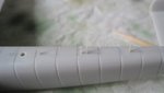
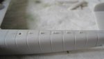
") ) I think I'm going to stick with my improvement on that part as is (to me it already is a vast improvement over the chunky airfix part.
) I think I'm going to stick with my improvement on that part as is (to me it already is a vast improvement over the chunky airfix part.Good work Jelmer. Never thought to offer - I have some scale plans I could have sent you!
 This books has all the scale plans I can possibly think of as far as the early types are concerned. With plenty more 110's in both 1/72 and 1/48 on the shelf and in progress this was a good investment + an interesting section about Wolfgang Falck which suits my particular areas of interest perfectly.
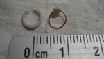
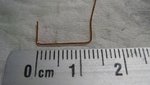
As for the D/F-loop antenna I think it will be very difficult to replicate a two-loop antenna in 1/72 scale. I guess you had the advantage of doing it in 1/48
Ah, yes. I did not realize it's 1/72. You're doing an excellent job on those details. Carry on then!