**** DONE: Bf109F-1, W.Nr. 5628, Werner Molders, Stab JG51, Me/FW Group Build.

Ad: This forum contains affiliate links to products on Amazon and eBay. More information in Terms and rules

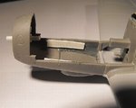
Nothing too catastrophic Glenn. With a little attention, they turn out great, unless of course you have warped bits but then evem my Tamiya He 219 had a bad warp in the wing.
 
Andy's right. The overall fit isn't too bad, they just need some attention and maybe a bit of coaxing, with a file! They turn out very well indeed, with some nice, finely detailed parts. Word of warning though - the plastic is quite soft and pliable, so care is needed, especially with delicate parts. The early releases gained a reputation for short-shots, flash, and missing detail, but that seems to have been cured now, which is possibly why the wing is a different colour, unless it's for the shape of the wheel wells, or both.
 
Thanks Evan.
Karl, I'm looking forward to how I do the nose! Test fitting shows it might be easier than I thought though, so fingers crossed. Hope to get it done tonight.
 
Got the first stage done, and it seems to be going well so far. Most reviews mention a gap, or misalignment, of the hinge line on the top of the main engine cowls, but a test fit shows this might not be the case with the engine omitted. I'll soon know!
PIC 1. Scraps of plastic card have been cemented into the nose to act as support/reinforcing spars for the front cowl section.
PIC 2. Whilst the spars were setting, the two halves of the nose section were cemented together, and a new prop shaft fabricated from plastic rod and tube, the latter to give some support and strength to the joint.
PICS 3 and 4. The nose section now cemented in place, after test-fitting the engine cowls to ensure correct alignment. When fully set, the joints will be cleaned up, and the lower joint removed, as this did not exist on the 'F'.
Next stage is to fit supports for the exhausts, fit the exhausts themselves, and then the main cowlings.
 

Attachments

  • Molders Bf109F 082.jpg
    Molders Bf109F 082.jpg
    42.6 KB · Views: 103
  • Molders Bf109F 078.jpg
    Molders Bf109F 078.jpg
    63.6 KB · Views: 106
  • Molders Bf109F 077.jpg
    Molders Bf109F 077.jpg
    50.8 KB · Views: 102
  • Molders Bf109F 081.jpg
    Molders Bf109F 081.jpg
    43.2 KB · Views: 105
Thanks Evan.
I'm happy to say that the entire nose is now assembled, and just needs a little 'tweaking' and tidying up.
PIC 1. Spaced mounts for the exhausts were glued inside the lower cowling, using scraps of plastic card.
PICS 2 and 3. The exhausts first had the locating pins removed from their inner faces, and were then cemented to the mounts, ensuring the correct ones were fitted to the correct sides! I had intended drilling-out the exhaust ports, but there wasn't much room for error, their being relatively thin, and the plastic being soft, so I didn't bother.
PICS 4 and 5. The exhaust shields in place, ensuring again the correct ones are placed on the correct side. The curved-down outer edge of the port shield had some annoying sprue attachment points to remove, the remains of which can be seen here, but will have a further light sanding when fully set.
PIC 6. The port engine cowl in place, but with the machine gun yet to be fitted. The cowl was cemented in place, and then the forward cowling pressed back on to it, and a thin bead of 'Superglue' run into the joint on the inside, to ensure it all lined up properly.
PIC 7. The barrels were cut off the kit MG17s, and cemented to the inside of each cowling half, ensuring that the correct one was used for each side, and that the blast tube trough extensions on the muzzles lined up with the cowling troughs.
PICS 8 and 9. Both engine cowlings in place and cemented, and awaiting clean-up and attention to any gaps. The starboard cowl needed a tiny amount of sanding on the lower, rear section, in order for it to 'sit' down onto the lower panel. The tiny gap along the upper central joint is deliberate, as I intend to add a thin length of stretched sprue here, to simulate the piano hinge.
So, no major drama, and fitting the cowls without the engine assembly can be done, with little trouble, if care is exercised.
Next stage is to clean up and attend to all the joints, then fit the supercharger intake, before moving on to the radiators, flaps and slats.
Thanks again for your interest and support, and I'll post another up-date soon.
 

Attachments

  • Molders Bf109F 090.jpg
    Molders Bf109F 090.jpg
    38.9 KB · Views: 99
  • Molders Bf109F 087.jpg
    Molders Bf109F 087.jpg
    51.1 KB · Views: 105
  • Molders Bf109F 093.jpg
    Molders Bf109F 093.jpg
    50.7 KB · Views: 102
  • Molders Bf109F 084.jpg
    Molders Bf109F 084.jpg
    61.3 KB · Views: 102
  • Molders Bf109F 096.jpg
    Molders Bf109F 096.jpg
    40 KB · Views: 94
  • Molders Bf109F 088.jpg
    Molders Bf109F 088.jpg
    43.4 KB · Views: 101
  • Molders Bf109F 086.jpg
    Molders Bf109F 086.jpg
    45.4 KB · Views: 100
  • Molders Bf109F 089.jpg
    Molders Bf109F 089.jpg
    45.1 KB · Views: 99
  • Molders Bf109F 095.jpg
    Molders Bf109F 095.jpg
    43.5 KB · Views: 104
Thanks Andy. I'll be using a combination of kit decals, a few from the spare decals files, and some from the Kagero 'Top drawings' Bf109F book that Wojtek sent me. I thought I might have to make the winkel, as the ones I have are slightly different angles to the profile, but one of the photos of one of Molders' 'Fs' shows a winkel very close to ones I have.
The two machines he used during this period were almost identical in paint and markings, except for the top decking camouflage line around the cockpit, and the winkels, so it should turn out OK I hope. Whether it'll be the same W.Nr is another matter !
EDIT: Crossing posts - thanks David !
 
Last edited:

Users who are viewing this thread

Back