**** DONE: Bf109F-1, W.Nr. 5628, Werner Molders, Stab JG51, Me/FW Group Build.

Ad: This forum contains affiliate links to products on Amazon and eBay. More information in Terms and rules
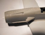
Not much to show at the moment. The stretched sprue 'hinge' has been fitted to the cowling top, and the supercharger intake attached, but most work at the moment is concentrating on sanding seams and joints. Should have some pics tomorrow, when the radiators might be in place.
 
OK, the lower nose joints have been filled and sanded where required, using 'Superglue', and the supercharger intake and stretched sprue hinge added. Some work has been done to improve the aileron surfaces, and work is underway fitting the radiator flaps.
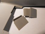
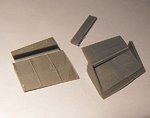
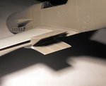
Most reviews mention these radiator parts, and reviewers seem to think they can't be assembled in any of the open positions, just closed. Well, it's a very easy job to modify the parts to give an acceptable appearance in the fully or part open positions, as the following pics will show.
PIC 1. Nose joints filled and sanded, supercharger intake, and the stretched sprue 'hinge' on top of the main cowling - and yes, this has since been straightened !!
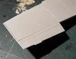
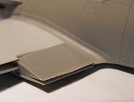
PIC 2. The ribs on the ailerons (and the rudder) are far too heavy, and these have been sanded back slightly. After priming, paint and clear coats, they should look more realistic.
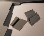
PICS 3 and 4. The radiator shutter parts as provided, and note the ejector pins on the inner surface of the top shutter.
PIC 5. The parts loosely fitted as per the kit instructions, neither fully closed or part open.
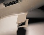
PIC 6. The curved front of the extension on the upper shutter was removed at the curve, and the 'block' for the radiator on the lower shutter was slightly chamfered on the front edge. The ejector pins have been removed from the inner face of the upper shutter,, and the reinforcing ribs added to the lower shutter, using stretched sprue, with paper fillets on the outer edges. These areas will be painted RLM02, and the radiator front and rear in a dark metallic colour, before cementing in place at the desired angles.
PICS 7 and 8. Trial fit of the modified parts. I would prefer to fit these after painting the model, but as the angles need to be adjusted before cementing, I have to fit these next.
Once this bit is completed, it'll be time to add the wing tips and slats, and then give some attention to the tail planes.
Thanks again for looking, and I'll post more soon.
 

Attachments

  • Molders Bf109F 109.jpg
    Molders Bf109F 109.jpg
    38 KB · Views: 105
  • Molders Bf109F 099.jpg
    Molders Bf109F 099.jpg
    37.2 KB · Views: 105
  • Molders Bf109F 101.jpg
    Molders Bf109F 101.jpg
    38.8 KB · Views: 100
  • Molders Bf109F 107.jpg
    Molders Bf109F 107.jpg
    49.4 KB · Views: 120
  • Molders Bf109F 108.jpg
    Molders Bf109F 108.jpg
    39.7 KB · Views: 111
  • Molders Bf109F 104.jpg
    Molders Bf109F 104.jpg
    46 KB · Views: 107
  • Molders Bf109F 102.jpg
    Molders Bf109F 102.jpg
    46.4 KB · Views: 103
  • Molders Bf109F 103.jpg
    Molders Bf109F 103.jpg
    39.3 KB · Views: 98
A fine job there Terry. The rad louvers look great and the toned down ribbing on the aileron surface looks "the biz". It's one of the first faults I noticed on initial inspection of the kit, the rudder being particularly nasty.
 
Thanks very much Maria and Peter.
Bit more progress to show.
PICS 1 and 2. The radiator assemblies painted and installed.
PIC 3. The engine inertia crank handle hole drilled out, and the small intake added from stretched sprue, cut to shape. Note that the rough-looking areas around the cowl joints have yet to be polished !
PIC 4. The holes for the jacking/lifting points drilled out on both sides.
PIC 5. The tail planes were lacking definition along the elevator hinge line, as noted in most reviews, so these were re-engraved. The elevator ribs however, were too 'heavy', so these were partially sanded back, and then the tail planes cemented in place.
PIC 6. How the model looks to date.
 

Attachments

  • Molders Bf109F 120.jpg
    Molders Bf109F 120.jpg
    34.5 KB · Views: 126
  • Molders Bf109F 113.jpg
    Molders Bf109F 113.jpg
    37.4 KB · Views: 127
  • Molders Bf109F 111.jpg
    Molders Bf109F 111.jpg
    45.1 KB · Views: 115
  • Molders Bf109F 115.jpg
    Molders Bf109F 115.jpg
    33.5 KB · Views: 117
  • Molders Bf109F 114.jpg
    Molders Bf109F 114.jpg
    50.5 KB · Views: 110
  • Molders Bf109F 118.jpg
    Molders Bf109F 118.jpg
    36.7 KB · Views: 124
Quick update.
PIC 1. The wing tips were test fitted, and showed a slight 'step' between the wing and the tip. This was filed and sanded, and then the tips cemented in place. I'm not that happy with the integral pitot, and may replace this with tubes.
PIC 2. Slight gaps were evident on the upper joints, more so on the port wing, shown here.
PICS 3 and 4. Once the tips had set, the gaps were filled with PVA and smoothed-off with a wet finger tip. Next stage is to mask the model as required, then tack in place the slats and flaps, before spraying overall in light grey primer, ready for the painting stage.
Thanks again for your interest and compliments, and I should have some more pics over the weekend.
 

Attachments

  • Molders Bf109F 126.jpg
    Molders Bf109F 126.jpg
    46.1 KB · Views: 114
  • Molders Bf109F 123.jpg
    Molders Bf109F 123.jpg
    34.2 KB · Views: 108
  • Molders Bf109F 122.jpg
    Molders Bf109F 122.jpg
    35.3 KB · Views: 110
  • Molders Bf109F 124.jpg
    Molders Bf109F 124.jpg
    35.5 KB · Views: 124

Users who are viewing this thread

Back